
Datasheet

PCA9670 All information provided in this document is subject to legal disclaimers. © NXP B.V. 2013. All rights reserved.
Product data sheet Rev. 3 — 30 May 2013 17 of 35
NXP Semiconductors
PCA9670
Remote 8-bit I/O expander for Fm+ I
2
C-bus with reset
{
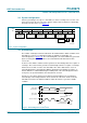
<S> <0100 0001> <ACK> <1010 0010> <NACK> <P> //Read PCA9670 data
If (P0 == 0) //Temperature sensor activated
{
// write to PCA9670 with data 0010 1011b to turn on LED (P7), on Switch (P3)
and keep P[1:0] as input ports.
<S> <0100 0000> <ACK> <0010 1011> <ACK> <P> // Write to PCA9670
Exit the loop;
}
}
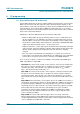
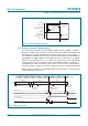
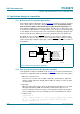
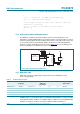
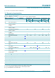
10.3 High current-drive load applications
The GPIO has a minimum guaranteed sinking current of 25 mA per bit at 5.5 V. In
applications requiring additional drive, two port pins may be connected together to sink up
to 50 mA current. Both bits must then always be turned on or off together. Up to 8 pins can
be connected together to drive 200 mA, which is the device recommended total limit.
Each pin needs its own limiting resistor as shown in Figure 20
to prevent damage to the
device should all ports not be turned on at the same time.
10.4 Migration path
NXP offers new, more capable drop-in replacements for the PCA9670 in newer
space-saving packages.
PCA9670 replaces the interrupt output of the PCA9674 with hardware reset input to retain
the maximum number of addresses. PCA9672 replaces address A2 of the PCA9674 with
hardware reset input to retain the interrupt, but limit the number of addresses.
Fig 20. High current-drive load application
002aac299
V
DD
P0
P1
P2
P3
P4
P5
P6
P7
V
DD
SDA
SCL
RESET
AD0
AD1
AD2
CORE
PROCESSOR
V
DD
LOAD
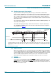
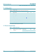
Table 5. PCA9670 migration path
Type number I
2
C-bus
frequency
Voltage range Number of
addresses
per device
Interrupt Reset Total package
sink current
PCF8574/74A 100 kHz 2.5 V to 6 V 8 yes no 80 mA
PCA8574/74A 400 kHz 2.3 V to 5.5 V 8 yes no 200 mA
PCA9674/74A 1 MHz Fm+ 2.3 V to 5.5 V 64 yes no 200 mA
PCA9670 1 MHz Fm+ 2.3 V to 5.5 V 64 no yes 200 mA
PCA9672 1 MHz Fm+ 2.3 V to 5.5 V 16 yes yes 200 mA