
Datasheet

PCA9670 All information provided in this document is subject to legal disclaimers. © NXP B.V. 2013. All rights reserved.
Product data sheet Rev. 3 — 30 May 2013 16 of 35
NXP Semiconductors
PCA9670
Remote 8-bit I/O expander for Fm+ I
2
C-bus with reset
10. Application design-in information
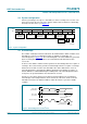
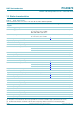
10.1 Bidirectional I/O expander applications
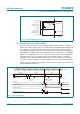
In the 8-bit I/O expander application shown in Figure 19, P0 and P1 are inputs, and P2 to
P7 are outputs. When used in this configuration, during a write, the input (P0 and P1)
must be written as HIGH so the external devices fully control the input ports. The
desired HIGH or LOW logic levels may be written to the I/Os used as outputs (P2 to P7).
If 10 A internal output HIGH is not enough current source, the port needs external pull-up
resistor. During a read, the logic levels of the external devices driving the input ports (P0
and P1) and the previous written logic level to the output ports (P2 to P7) will be read.
The GPIO also has a reset line (RESET
) that can be connected to an output pin of the
microprocessor. Since the device does not have an interrupt output, changes of the I/Os
can be monitored by reading the input register. If both a RESET
and INT are needed, use
the PCA9672.
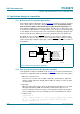
10.2 How to read and write to I/O expander (example)
In the application example of PCA9670 shown in Figure 19, the microcontroller wants to
control the P3 switch ON and the P7 LED ON when the temperature sensor P0 changes.
1. When the system power on:
Core Processor needs to issue an initial command to set P0 and P1 as inputs and
P[7:2] as outputs with value 1010 00 (LED off, MP3 off, camera on, audio off, switch
off and latch off).
2. Operation:
When the temperature changes above the threshold, the temperature sensor signal
will toggle from HIGH to LOW. The INT will be activated and notifies the ‘core
processor’ that there have been changes on the input pins. Read the input register.
If P0 = 0 (temperature sensor has changed), then turn on LED and turn on switch.
3. Software code:
//System Power on
// write to PCA9670 with data 1010 0011b to set P[7:2] outputs and P[1:0] inputs
<S> <0100 0000> <ACK> <1010 0011> <ACK> <P>//Initial setting for PCA9670
while (1) //Looping look for P0 = 0
Fig 19. Bidirectional I/O expander application
002aac298
V
DD
temperature sensor
battery status
control for latch
control for switch
control for audio
control for camera
control for MP3
P0
P1
P2
P3
P4
P5
P6
P7
V
DD
SDA
SCL
RESET
AD0
AD1
AD2
CORE
PROCESSOR
V
DD