
Datasheet


PCA9535A All information provided in this document is subject to legal disclaimers. © NXP B.V. 2012. All rights reserved.
Product data sheet Rev. 1 — 11 September 2012 15 of 38
NXP Semiconductors
PCA9535A
Low-voltage 16-bit I
2
C-bus I/O port with interrupt
8.2 Power-on reset requirements
In the event of a glitch or data corruption, PCA9535A can be reset to its default conditions
by using the power-on reset feature. Power-on reset requires that the device go through a
power cycle to be completely reset. This reset also happens when the device is
powered on for the first time in an application.
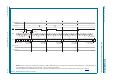
The two types of power-on reset are shown in Figure 15
and Figure 16.
Table 13 specifies the performance of the power-on reset feature for PCA9535A for both
types of power-on reset.
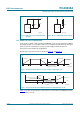
Fig 13. High value resistor in parallel with
the LED
Fig 14. Device supplied by a lower voltage
002aag164
LED
V
DD
Pn
100 kΩ
V
DD
002aag165
LED
V
DD
Pn
3.3 V 5 V
Fig 15. V
DD
is lowered below 0.2 V or to 0 V and then ramped up to V
DD
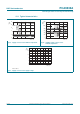
Fig 16. V
DD
is lowered below the POR threshold, then ramped back up to V
DD
002aah329
V
DD
time
ramp-up ramp-down
(dV/dt)
r
(dV/dt)
f
re-ramp-up
(dV/dt)
r
time to re-ramp
when V
DD
drops
below 0.2 V or to V
SS
t
d(rst)
002aah330
V
DD
time
ramp-down
(dV/dt)
f
ramp-up
(dV/dt)
r
time to re-ramp
when V
DD
drops
to V
POR(min)
− 50 mV
t
d(rst)
V
I
drops below POR levels