
Datasheet

PCA9515A All information provided in this document is subject to legal disclaimers. © NXP B.V. 2012. All rights reserved.
Product data sheet Rev. 5 — 23 March 2012 9 of 20
NXP Semiconductors
PCA9515A
I
2
C-bus repeater
10. Dynamic characteristics
[1] Typical values taken at V
CC
= 2.5 V and T
amb
=25C.
[2] Different load resistance and capacitance will alter the RC time constant, thereby changing the propagation delay and transition times.
[1] Typical values taken at V
CC
= 3.3 V and T
amb
=25C.
[2] Different load resistance and capacitance will alter the RC time constant, thereby changing the propagation delay and transition times.
10.1 AC waveforms
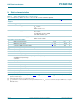
Table 6. Dynamic characteristics (V
CC
= 2.3 V to 2.7 V)
V
CC
= 2.3 V to 2.7 V; GND = 0 V; T
amb
=
40
Cto+85
C; unless otherwise specified.
Symbol Parameter Conditions Min Typ
[1]
Max Unit
t
PHL
HIGH to LOW propagation delay Figure 8 45 82 130 ns
t
PLH
LOW to HIGH propagation delay Figure 8
[2]
33 113 190 ns
t
THL
HIGH to LOW output transition time Figure 8 -57-ns
t
TLH
LOW to HIGH output transition time Figure 8
[2]
-148-ns
t
su
set-up time EN HIGH before START condition 100 - - ns
t
h
hold time EN HIGH after STOP condition 130 - - ns
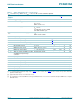
Table 7. Dynamic characteristics (V
CC
= 3.0 V to 3.6 V)
V
CC
= 3.0 V to 3.6 V; GND = 0 V; T
amb
=
40
Cto+85
C; unless otherwise specified.
Symbol Parameter Conditions Min Typ
[1]
Max Unit
t
PHL
HIGH to LOW propagation delay Figure 8 45 68 120 ns
t
PLH
LOW to HIGH propagation delay Figure 8
[2]
33 102 180 ns
t
THL
HIGH to LOW output transition time Figure 8 -58-ns
t
TLH
LOW to HIGH output transition time Figure 8
[2]
-147-ns
t
su
set-up time EN HIGH before START condition 100 - - ns
t
h
hold time EN HIGH after STOP condition 100 - - ns
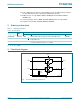
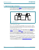
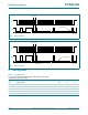
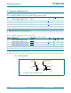
Fig 8. Propagation delay and transition times
002aad478
3.3 V
3.3 V
t
PLH
t
THL
1.5 V 1.5 Vinput
output
20 %
1.5 V
1.5 V
80 %
20 %
80 %
t
PHL
t
TLH
V
OL
0.1 V