
Single-Chip Microcontroller User Manual


UM10310_1 © NXP B.V. 2008. All rights reserved.
User manual Rev. 01 — 1 December 2008 6 of 139
NXP Semiconductors
UM10310
P89LPC9321 User manual
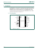
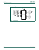
P1.0/TXD 18 I/O P1.0 — Port 1 bit 0.
O TXD — Transmitter output for serial port.
P1.1/RXD 17 I/O P1.1 — Port 1 bit 1.
I RXD — Receiver input for serial port.
P1.2/T0/SCL 12 I/O P1.2 — Port 1 bit 2 (open-drain when used as output).
I/O T0 — Timer/counter 0 external count input or overflow output (open-drain when
used as output).
I/O SCL — I
2
C-bus serial clock input/output.
P1.3/INT0
/SDA 11 I/O P1.3 — Port 1 bit 3 (open-drain when used as output).
I INT0
— External interrupt 0 input.
I/O SDA — I
2
C-bus serial data input/output.
P1.4/INT1
10 I/O P1.4 — Port 1 bit 4. High current source.
I INT1
— External interrupt 1 input.
P1.5/RST
6IP1.5 — Port 1 bit 5 (input only).
I RST
— External Reset input during power-on or if selected via UCFG1. When
functioning as a reset input, a LOW on this pin resets the microcontroller, causing
I/O ports and peripherals to take on their default states, and the processor begins
execution at address 0. Also used during a power-on sequence to force ISP
mode.
P1.6/OCB 5 I/O P1.6 — Port 1 bit 6. High current source.
O OCB — Output Compare B
P1.7/OCC 4 I/O P1.7 — Port 1 bit 7. High current source.
O OCC — Output Compare C.
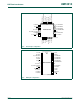
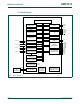
P2.0 to P2.7 I/O Port 2: Port 2 is an 8-bit I/O port with a user-configurable output type. During reset
Port 2 latches are configured in the input only mode with the internal pull-up
disabled. The operation of Port 2 pins as inputs and outputs depends upon the
port configuration selected. Each port pin is configured independently. Refer to
Section 4.1 “
Port configurations” for details.
All pins have Schmitt triggered inputs.
Port 2 also provides various special functions as described below:
P2.0/ICB 1 I/O P2.0 — Port 2 bit 0.
I ICB — Input Capture B.
P2.1/OCD 2 I/O P2.1 — Port 2 bit 1.
O OCD — Output Compare D.
P2.2/MOSI 13 I/O P2.2 — Port 2 bit 2.
I/O MOSI — SPI master out slave in. When configured as master, this pin is output;
when configured as slave, this pin is input.
P2.3/MISO 14 I/O P2.3 — Port 2 bit 3.
I/O MISO — When configured as master, this pin is input, when configured as slave,
this pin is output.
P2.4/SS
15 I/O P2.4 — Port 2 bit 4.
I/O SS
— SPI Slave select.
Table 1. Pin description
…continued
Symbol Pin Type Description