
Single-Chip Microcontroller User Manual


UM10310_1 © NXP B.V. 2008. All rights reserved.
User manual Rev. 01 — 1 December 2008 34 of 139
NXP Semiconductors
UM10310
P89LPC9321 User manual
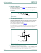
For correct activation of Brownout Detect, certain V
DD
rise and fall times must be
observed. Please see the data sheet for specifications.
5.2 Power-on detection
The Power-On Detect has a function similar to the Brownout Detect, but is designed to
work as power initially comes up, before the power supply voltage reaches a level where
the Brownout Detect can function. The POF flag (RSTSRC.4) is set to indicate an initial
power-on condition. The POF flag will remain set until cleared by software by writing a
logic 0 to the bit. BOF (RSTSRC.5) will be set when POF is set.
5.3 Power reduction modes
The P89LPC9321 supports three different power reduction modes as determined by SFR
bits PCON[1:0] (see Table 17
).
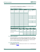
Table 15. BOD Trip points configuration
BOE1
(UCFG1.5)
BOE0
(UCFG1.3)
BOICFG1
(BOICFG.1)
BOICFG0
(BOICFG.0)
BOD Reset
BOD
Interrupt
00 0 0 Reserved
00 0 1
00 1 0
00 1 1
01 0 0
0 1 0 1 2.2V 2.4V
0 1 1 0 2.2V 2.6V
0 1 1 1 2.2V 3.2V
10 0 0 Reserved
10 0 1
1 0 1 0 2.4V 2.6V
1 0 1 1 2.4V 3.2V
11 0 0 Reserved
11 0 1
11 1 0
1 1 1 1 3.0V 3.2V
Table 16. BOD Reset and BOD Interrupt configuration
PMOD1/PMOD0(PCON[1:0]) BOI
(PCON.4)
EBO
(IEN0.5)
EA
(IEN0.7)
BOD
Reset
BOD
Interrupt
11 (total power-down) X X X N N
≠ 11 (any mode other than total
power down)
0XXYN
10XYN
X0YN
11YY