
Single-Chip Microcontroller User Manual


xxxxxxxxxxxxxxxxxxxxx xxxxxxxxxxxxxxxxxxxxxxxxxx xxxxxxx x x x xxxxxxxxxxxxxxxxxxxxxxxxxxxxxx xxxxxxxxxxxxxxxxxxx xx xx xxxxx
xxxxxxxxxxxxxxxxxxxxxxxxxxx xxxxxxxxxxxxxxxxxxx xxxxxx xxxxxxxxxxxxxxxxxxxxxxxxxxxxxxxxxxx xxxxxxxxxxxx x x
xxxxxxxxxxxxxxxxxxxxx xxxxxxxxxxxxxxxxxxxxxxxxxxxxxx xxxxx xxxxxxxxxxxxxxxxxxxxxxxxxxxxxxxxxxxxxxxxxxxxxxxxxx xxxxxxxx
xxxxxxxxxxxxxxxxxxxxxxxxx xxxxxxxxxxxxxxxxxxxx xxx
UM10310_1 © NXP B.V. 2008. All rights reserved.
User manual Rev. 01 — 1 December 2008 18 of 139
NXP Semiconductors
UM10310
P89LPC9321 User manual
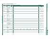
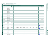
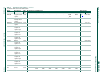
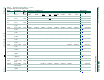
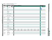
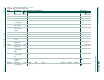
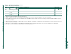
[1] All ports are in input only (high-impedance) state after power-up.
[2] BRGR1 and BRGR0 must only be written if BRGEN in BRGCON SFR is logic 0. If any are written while BRGEN = 1, the result is unpredictable.
[3] The RSTSRC register reflects the cause of the UM10310 reset except BOIF bit. Upon a power-up reset, all reset source flags are cleared except POF and BOF; the power-on
reset value is x011 0000.
[4] After reset, the value is 1110 01x1, i.e., PRE2 to PRE0 are all logic 1, WDRUN = 1 and WDCLK = 1. WDTOF bit is logic 1 after watchdog reset and is logic 0 after power-on reset.
Other resets will not affect WDTOF.
[5] On power-on reset and watchdog reset, the TRIM SFR is initialized with a factory preprogrammed value. Other resets will not cause initialization of the TRIM register.
[6] The only reset sources that affect these SFRs are power-on reset and watchdog reset.
WDL Watchdog load C1H FF 1111 1111
WFEED1 Watchdog
feed 1
C2H
WFEED2 Watchdog
feed 2
C3H
Table 2. Special function registers …continued
* indicates SFRs that are bit addressable.
Name Description SFR
addr.
Bit functions and addresses Reset value
MSB LSB Hex Binary