
Datasheet


P82B715_8 © NXP B.V. 2009. All rights reserved.
Product data sheet Rev. 08 — 9 November 2009 2 of 23
NXP Semiconductors
P82B715
I
2
C-bus extender
n Supply voltage range 3 V to 12 V
n Clock speeds to at least 100 kHz and 400 kHz when other system delays permit
n ESD protection exceeds 2500 V HBM per Mil. Std 883C-3015.7 and 400 V MM per
JESD22-A115 (I/Os have diodes to V
CC
and GND)
n Latch-up testing is done to JEDEC Standard JESD78 which exceeds 100 mA
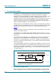
3. Applications
n Increase the total connected capacitance of an I
2
C-bus system to around 3000 pF
n Drive I
2
C-bus signals over long cables to approximately 50 meters or 3000 pF
n Drives ×10 lower impedance bus wiring for improved noise immunity
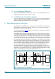
n Multi-drop distribution of I
2
C-bus signals using low cost twisted-pair cables
n AdvancedTCA radial IPMB architecture
n Driving 30 mA Fm+ devices from standard 3 mA parts
4. Ordering information
[1] For applications requiring lower voltage operation, or additional buffer performance, see application notes
AN255, “I
2
C/SMBus repeaters, hubs and expanders”
and
AN10710, “Features and applications of the
P82B715 I
2
C-bus extender”
.
4.1 Ordering options
Table 1. Ordering information
[1]
Type number Package
Name Description Version
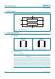
P82B715PN DIP8 plastic dual in-line package; 8 leads (300 mil) SOT97-1
P82B715TD SO8 plastic small outline package; 8 leads; body width 3.9 mm SOT96-1
Table 2. Ordering options
Type number Topside mark Temperature range
P82B715PN P82B715PN −40 °C to +85 °C
P82B715TD P82B715 −40 °C to +85 °C