
Datasheet


MPC8309 PowerQUICC II Pro Integrated Communications Processor Family Hardware Specifications, Rev. 2
Freescale Semiconductor 71
Thermal
T
A
= ambient temperature for the package (°C)
R
θ
JA
= junction-to-ambient thermal resistance (°C/W)
P
D
= power dissipation in the package (W)
The junction-to-ambient thermal resistance is an industry standard value that provides a quick and easy
estimation of thermal performance. As a general statement, the value obtained on a single layer board is
appropriate for a tightly packed printed-circuit board. The value obtained on the board with the internal
planes is usually appropriate if the board has low power dissipation and the components are well separated.
Test cases have demonstrated that errors of a factor of two (in the quantity T
J
– T
A
) are possible.
24.1.3 Estimation of junction temperature with junction-to-board thermal
resistance
The thermal performance of a device cannot be adequately predicted from the junction-to-ambient thermal
resistance. The thermal performance of any component is strongly dependent on the power dissipation of
surrounding components. In addition, the ambient temperature varies widely within the application. For
many natural convection and especially closed box applications, the board temperature at the perimeter
(edge) of the package is approximately the same as the local air temperature near the device. Specifying
the local ambient conditions explicitly as the board temperature provides a more precise description of the
local ambient conditions that determine the temperature of the device.
At a known board temperature, the junction temperature is estimated using the following equation:
T
J
=T
B
+(R
θ
J
B
×
P
D
)Eqn.2
where,
T
J
= junction temperature (°C)
T
B
= board temperature at the package perimeter (°C)
R
θ
JB
= junction-to-board thermal resistance (°C/W) per JESD51-8
P
D
= power dissipation in package (W)
When the heat loss from the package case to the air can be ignored, acceptable predictions of junction
temperature can be made. The application board should be similar to the thermal test condition: the
component is soldered to a board with internal planes.
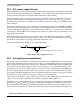
24.1.4 Experimental determination of junction temperature
To determine the junction temperature of the device in the application after prototypes are available, the
thermal characterization parameter (Ψ
JT
) can be used to determine the junction temperature with a
measurement of the temperature at the top center of the package case using the following equation:
T
J
=T
T
+(
Ψ
JT
×
P
D
)Eqn.3
where,
T
J
= junction temperature (°C)