
Datasheet


MPC8309 PowerQUICC II Pro Integrated Communications Processor Family Hardware Specifications, Rev. 2
Freescale Semiconductor 69
Clocking
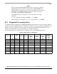
NOTE
The VCO divider (RCWL[CEVCOD]) must be set properly so that the
QUICC Engine VCO frequency is in the range of 300–600 MHz. The
QUICC Engine frequency is not restricted by the CSB and core frequencies.
The CSB, core, and QUICC Engine frequencies should be selected
according to the performance requirements.
The QUICC Engine VCO frequency is derived from the following
equations:
qe_clk = (primary clock input × CEPMF) ÷ (1 + CEPDF)
QUICC Engine VCO Frequency = qe_clk × VCO divider × (1 + CEPDF)
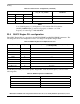
23.7 Suggested PLL configurations
To simplify the PLL configurations, the MPC8309 might be separated into two clock domains. The first
domain contains the CSB PLL and the core PLL. The core PLL is connected serially to the CSB PLL, and
has the csb_clk as its input clock. The second clock domain has the QUICC Engine PLL. The clock
domains are independent, and each of their PLLs is configured separately.
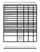
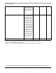
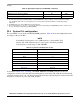
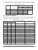
The following table shows suggested PLL configurations for 33 and 66 MHz input clocks.
Table 61. Suggested PLL configurations
Conf No. SPMF
Core
PLL
CEPMF CEDF
Input Clock
Frequency
(MHz)
CSB
Frequency
(MHz)
Core
Frequency
(MHz)
QUICC
Engine
Frequency
(MHz)
1
0100 0000100 0111 0 33.33 133.33 266.66 233
2
0010 0000100 0111 1 66.67 133.33 266.66 233
3
0100 0000101 0111 0 33.33 133.33 333.33 233
4
0101 0000101 1001 0 25 125 312.5 225
5
0010 0000101 0111 1 66.67 133.33 333.33 233
6
0100 0000110 0111 0 33.33 133.33 399.96 233
7
0101 0000110 1000 0 25 125 375 225
8
0010 0000110 0011 0 66.67 133.33 399.96 233
9
0101 0000101 0111 0 33.33 166.67 416.67 233