
Datasheet

MPC8309 PowerQUICC II Pro Integrated Communications Processor Family Hardware Specifications, Rev. 2
44 Freescale Semiconductor
IPIC
19 IPIC
This section describes the DC and AC electrical specifications for the external interrupt pins of the
MPC8309.
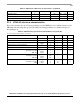
19.1 IPIC DC electrical characteristics
The following table provides the DC electrical characteristics for the external interrupt pins of the
MPC8309.
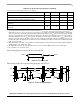
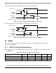
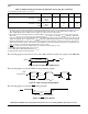
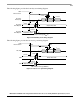
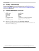
19.2 IPIC AC timing specifications
The following table provides the IPIC input and output AC timing specifications.
20 SPI
This section describes the DC and AC electrical specifications for the SPI of the MPC8309.
20.1 SPI DC electrical characteristics
The following table provides the DC electrical characteristics for the MPC8309 SPI.
Table 47. IPIC DC electrical characteristics
1,2
Characteristic Symbol Condition Min Max Unit
Input high voltage V
IH
—2.0OV
DD
+0.3 V
Input low voltage V
IL
— –0.3 0.8 V
Input current I
IN
——±5μA
Output High Voltage V
OH
I
OL
= -8.0 mA 2.4 — V
Output low voltage V
OL
I
OL
= 6.0 mA — 0.5 V
Output low voltage V
OL
I
OL
= 3.2 mA — 0.4 V
Notes:
1. This table applies for pins IRQ
, MCP_OUT, and QE ports Interrupts.
2. MCP_OUT
is open drain pins, thus V
OH
is not relevant for those pins.
Table 48. IPIC Input AC timing specifications
1
Characteristic Symbol
2
Min Unit
IPIC inputs—minimum pulse width t
PIWID
20 ns
Notes:
1. Input specifications are measured from the 50% level of the signal to the 50% level of the rising edge of SYS_CLK_IN.
Timings are measured at the pin.
2. IPIC inputs and outputs are asynchronous to any visible clock. IPIC outputs should be synchronized before use by any
external synchronous logic. IPIC inputs are required to be valid for at least t
PIWID
ns to ensure proper operation when working
in edge triggered mode.