
Datasheet


MPC8309 PowerQUICC II Pro Integrated Communications Processor Family Hardware Specifications, Rev. 2
Freescale Semiconductor 37
eSDHC
14 eSDHC
This section describes the DC and AC electrical specifications for the eSDHC interface of the device.
14.1 eSDHC DC electrical characteristics
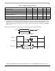
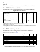
The following table provides the DC electrical characteristics for the eSDHC interface.
14.2 eSDHC AC timing specifications
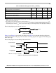
The following table provides the eSDHC AC timing specifications as defined in Figure 28 and Figure 29.
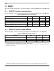
Table 37. eSDHC Interface DC electrical characteristics
At recommended operating conditions with OV
DD
=3.3V
Characteristic Symbol Condition Min Max Unit Note
Input high voltage V
IH
—0.625× OV
DD
—V1
Input low voltage V
IL
— — 0.25 × OV
DD
V1
Output high voltage V
OH
I
OH
= –100 μA at
OV
DD
min
0.75 × OV
DD
—V—
Output low voltage V
OL
I
OL
= 100 μA at
OV
DD
min
— 0.125 × OV
DD
V—
Output high voltage V
OH
I
OH
= –100 mA OV
DD
–0.2 — V 2
Output low voltage V
OL
I
OL
=2mA — 0.3 V 2
Input/output leakage current I
IN
/I
OZ
—–1010μA—
Notes:
1. Note that the min V
IL
and max V
IH
values are based on the respective min and max OV
IN
values found in Table 2..
2. Open drain mode for MMC cards only.
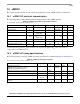
Table 38. eSDHC AC timing specifications
At recommended operating conditions with OV
DD
=3.3V
Parameter Symbol
1
Min Max Unit Notes
SD_CLK clock frequency:
SD/SDIO Full-speed/High-speed mode
MMC Full-speed/High-speed mode
f
SHSCK
0 25/33.25
20/52
MHz 2, 4
SD_CLK clock low time—Full-speed/High-speed mode t
SHSCKL
10/7 — ns 4
SD_CLK clock high time—Full-speed/High-speed mode t
SHSCKH
10/7 — ns 4
SD_CLK clock rise and fall times t
SHSCKR/
t
SHSCKF
—3ns4
Input setup times: SD_CMD, SD_DATx, SD_CD to
SD_CLK
t
SHSIVKH
5—ns4