
Datasheet


MPC8309 PowerQUICC II Pro Integrated Communications Processor Family Hardware Specifications, Rev. 2
Freescale Semiconductor 33
PCI
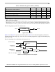
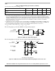
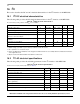
Figure 23 provides the AC test load for PCI.
Figure 23. PCI AC test load
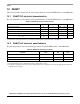
Table 31. PCI AC timing specifications at 66 MHz
Parameter Symbol
1
Min Max Unit Notes
Clock to output valid t
PCKHOV
—6.0ns2
Output hold from clock
t
PCKHOX
1—ns2
Clock to output high impedance t
PCKHOZ
—14ns2, 3
Input setup to clock t
PCIVKH
3.0 — ns 2, 4
Input hold from clock t
PCIXKH
0—ns2, 4
Notes:
1. The symbols used for timing specifications follow the pattern of t
(first two letters of functional block)(signal)(state)(reference)(state)
for
inputs and t
(first two letters of functional block)(reference)(state)(signal)(state)
for outputs. For example, t
PCIVKH
symbolizes PCI timing
(PC) with respect to the time the input signals (I) reach the valid state (V) relative to the PCI_SYNC_IN clock, t
SYS
, reference
(K) going to the high (H) state or setup time. Also, t
PCRHFV
symbolizes PCI timing (PC) with respect to the time hard reset
(R) went high (H) relative to the frame signal (F) going to the valid (V) state.
2. See the timing measurement conditions in the
PCI 2.3 Local Bus Specifications
.
3. For purposes of active/float timing measurements, the Hi-Z or off state is defined to be when the total current delivered
through the component pin is less than or equal to the leakage current specification.
4. Input timings are measured at the pin.
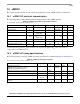
Table 32. PCI AC timing specifications at 33 MHz
Parameter Symbol
1
Min Max Unit Notes
Clock to output valid t
PCKHOV
—11ns2
Output hold from clock
t
PCKHOX
2—ns2
Clock to output high impedance t
PCKHOZ
—14ns2, 3
Input setup to clock t
PCIVKH
3.0 — ns 2, 4
Input hold from clock t
PCIXKH
0—ns2, 4
Notes:
1. The symbols used for timing specifications follow the pattern of t
(first two letters of functional block)(signal)(state)(reference)(state)
for
inputs and t
(first two letters of functional block)(reference)(state)(signal)(state)
for outputs. For example, t
PCIVKH
symbolizes PCI timing
(PC) with respect to the time the input signals (I) reach the valid state (V) relative to the PCI_SYNC_IN clock, t
SYS
, reference
(K) going to the high (H) state or setup time. Also, t
PCRHFV
symbolizes PCI timing (PC) with respect to the time hard reset
(R) went high (H) relative to the frame signal (F) going to the valid (V) state.
2. See the timing measurement conditions in the
PCI 2.3 Local Bus Specifications
.
3. For purposes of active/float timing measurements, the Hi-Z or off state is defined to be when the total current delivered
through the component pin is less than or equal to the leakage current specification.
4. Input timings are measured at the pin.
Output
Z
0
= 50 Ω
OV
DD
/2
R
L
= 50 Ω