
Datasheet


Chapter 12 Development Support
MC9RS08KA2 Series Data Sheet, Rev. 4
100 Freescale Semiconductor
The BDC serial communication protocol requires the host to know the target BDC clock speed.
Commands and data are sent most significant bit first (MSB-first) at 16 BDC clock cycles per bit. The
interface times out if 512 BDC clock cycles occur between falling edges from the host. Any BDC
command that was in progress when this timeout occurs is aborted without affecting the memory or
operating mode of the target MCU system.
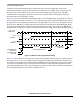
Figure 12-3 shows an external host transmitting a logic 1 or 0 to the BKGD pin of a target MCU. The host
is asynchronous to the target so there is a 0-to-1 cycle delay from the host-generated falling edge to where
the target perceives the beginning of the bit time. Ten target BDC clock cycles later, the target senses the
bit level on the BKGD pin. Typically, the host actively drives the pseudo-open-drain BKGD pin during
host-to-target transmissions to speed up rising edges. Because the target does not drive the BKGD pin
during the host-to-target period, there is no need to treat the line as an open-drain signal during this period.
Figure 12-3. BDC Host-to-Target Serial Bit Timing
Figure 12-4 shows the host receiving a logic 1 from the target MCU. Because the host is asynchronous to
the target, there is a 0-to-1 cycle delay from the host-generated falling edge on BKGD to the perceived
start of the bit time in the target. The host holds the BKGD pin low long enough for the target to recognize
it (at least two target BDC cycles). The host must release the low drive before the target drives a brief
active-high speedup pulse seven cycles after the perceived start of the bit time. The host must sample the
bit level approximately 10 cycles after it started the bit time.
EARLIEST START
TARGET SENSES BIT LEVEL
10 CYCLES
SYNCHRONIZATION
UNCERTAINTY
BDC CLOCK
(TARGET MCU)
HOST
TRANSMIT 1
HOST
TRANSMIT 0
PERCEIVED START
OF BIT TIME
OF NEXT BIT