
Datasheet


Timebase Module (TBM)
MC68HC908GP32 Data Sheet, Rev. 10
196 Freescale Semiconductor
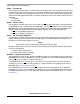
Figure 16-1. Timebase Block Diagram
16.4 Timebase Register Description
The timebase has one register, the TBCR, which is used to enable the timebase interrupts and set the
rate.
TBIF — Timebase Interrupt Flag
This read-only flag bit is set when the timebase counter has rolled over.
1 = Timebase interrupt pending
0 = Timebase interrupt not pending
Address: $001C
Bit 7654321Bit 0
Read: TBIF
TBR2 TBR1 TBR0
0
TBIE TBON R
Write: TACK
Reset:00000000
= Unimplemented R = Reserved
Figure 16-2. Timebase Control Register (TBCR)
÷ 2
SEL
0 0 0
0 0 1
0 1 0
0 1 1
TBIF
TBR1
TBR0
TBIE
TBON
R
TACK
TBR2
1 0 0
1 0 1
1 1 0
1 1 1
CGMXCLK
÷ 2 ÷ 2 ÷ 2 ÷ 2 ÷ 2 ÷ 2
÷ 2 ÷ 2 ÷ 2 ÷ 2 ÷ 2 ÷ 2 ÷ 2 ÷ 2
÷ 8 ÷ 16 ÷ 32 ÷ 64 ÷ 128
÷ 2048 ÷ 8192 ÷ 32768
TBMINT