
Datasheet

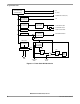

Serial Peripheral Interface (SPI)
MC68HC711D3 Data Sheet, Rev. 2.1
82 Freescale Semiconductor
CPOL — Clock Polarity Bit
When the clock polarity bit is cleared and data is not being transferred, the SCK pin of the master
device has a steady state low value. When CPOL is set, SCK idles high. Refer to Figure 7-2 and 7.4
Clock Phase and Polarity Controls.
CPHA — Clock Phase Bit
The clock phase bit, in conjunction with the CPOL bit, controls the clock-data relationship between
master and slave. The CPHA bit selects one of two different clocking protocols. Refer to Figure 7-2
and 7.4 Clock Phase and Polarity Controls.
SPR1 and SPR0 — SPI Clock Rate Select Bits
These two serial peripheral rate bits select one of four baud rates to be used as SCK if the device is a
master; however, they have no effect in the slave mode.
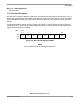
7.7.2 SPI Status Register
SPIF — SPI Transfer Complete Flag
SPIF is set upon completion of data transfer between the processor and the external device. If SPIF
goes high, and if SPIE is set, a serial peripheral interrupt is generated. To clear the SPIF bit, read the
SPSR with SPIF set, then access the SPDR. Unless SPSR is read (with SPIF set) first, attempts to
write SPDR are inhibited.
WCOL — Write Collision Bit
Clearing the WCOL bit is accomplished by reading the SPSR (with WCOL set) followed by an access
of SPDR. Refer to 7.5.4 Slave Select (SS) and 7.6 SPI System Errors.
0 = No write collision
1 = Write collision
Bit 5 — Not implemented
Always reads 0.
MODF — Mode Fault Bit
To clear the MODF bit, read the SPSR (with MODF set), then write to the SPCR. Refer to 7.5.4 Slave
Select (SS) and 7.6 SPI System Errors.
0 = No mode fault
1 = Mode fault
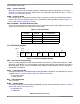
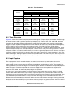
Table 7-1. SPI Clock Rates
SPR1
and SPR0
E Clock
Divide By
Frequency at
E = 2 MHz (Baud)
0 0 2 1.0 MHz
0 1 4 500 kHz
1 0 16 125 kHz
1 1 32 62.5 kHz
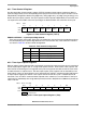
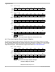
Address: $0029
Bit 7654321Bit 0
Read:
SPIFWCOL0MODF0000
Write:
Reset:00000000
Figure 7-4. SPI Status Register (SPSR)