
Datasheet


SCI Registers
MC68HC711D3 Data Sheet, Rev. 2.1
Freescale Semiconductor 73
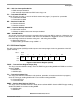
SCP1 and SCP0 — SCI Baud Rate Prescaler Select Bits
These two bits select a prescale factor for the SCI baud rate generator that determines the highest
possible baud rate.
SCR2–SCR0 — SCI Baud Rate Select Bits
These three bits select receiver and transmitter bit rate based on output from baud rate prescaler
stage.
The prescale bits, SCP1 and SCP0, determine the highest baud rate and the SCR2–SCR0 bits select
an additional binary submultiple (÷1, ÷2, ÷4, through ÷128) of this highest baud rate. The result of these
two dividers in series is the 16 X receiver baud rate clock. The SCR2–SCR0 bits are not affected by
reset and can be changed at any time, although they should not be changed when any SCI transfer is
in progress.
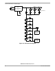
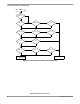
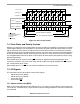
Figure 6-8 illustrates the SCI baud rate timing chain. The prescale select bits determine the highest
baud rate. The rate select bits determine additional divide by two stages to arrive at the receiver timing
(RT) clock rate. The baud rate clock is the result of dividing the RT clock by 16.
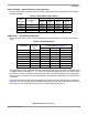
Table 6-1. Baud Rate Prescale Selects
SCP1
and SCP0
Divide
Internal Clock
By
Crystal Frequency in MHz
4.0 MHz
(Baud)
8.0 MHz
(Baud)
10.0 MHz
(Baud)
12.0 MHz
(Baud)
0 0 1 62.50 K 125.0 K 156.25 K 187.5 K
0 1 3 20.83 K 41.67 K 52.08 K 62.5 K
1 0 4 15.625 K 31.25 K 38.4 K 46.88 K
1 1 13 4800 9600 12.02 K 14.42 K
Table 6-2. Baud Rate Selects
SCR2–SCR0
Divide
Prescaler
By
Highest Baud Rate
(Prescaler Output from Table 6-1)
4800 9600 38.4 K
0 0 0 1 4800 9600 38.4 K
0 0 1 2 2400 4800 19.2 K
0 1 0 4 1200 2400 9600
0 1 1 8 600 1200 4800
1 0 0 16 300 600 2400
1 0 1 32 150 300 1200
1 1 0 64 — 150 600
1 1 1 128 — — 300