
Datasheet

Interrupts
MC68HC711D3 Data Sheet, Rev. 2.1
Freescale Semiconductor 59
NOTE
To prevent bus conflicts, when using internal read visibility, the user must
disable all external devices from driving the data bus during any internal
access.
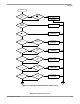
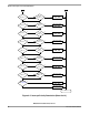
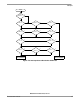
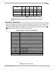
PSEL3–PSEL0 — Priority Selects
These four bits are used to specify one I bit related interrupt source, which then becomes the highest
priority I bit related interrupt source. These bits may be written only while the I bit in the CCR is set,
inhibiting I bit related interrupts. An interpretation of the value of these bits is shown in Table 4-4.
During reset, PSEL3–PSEL0 are initialized to 0101, which corresponds to reserved (default to IRQ
).
IRQ
becomes the highest priority I bit related interrupt source.
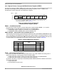
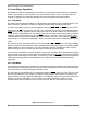
Mode
IRVNE
Out
of Reset
E Clock
Out
of Reset
IRV
Out
of Reset
IRVNE
Affects
Only
IRVNE
May
be Written
Single chip 0 On Off E Once
Expanded multiplexed 0 On Off IRV Once
Bootstrap 0 On Off E Once
Special test 1 On On IRV Once
Table 4-4. Highest Priority Interrupt Selection
PSEL3–PSEL0 Interrupt Source Promoted
0 0 0 0 Timer overflow
0 0 0 1 Pulse accumulator overflow
0 0 1 0 Pulse accumulator input edge
0 0 1 1 SPI serial transfer complete
0 1 0 0 SCI serial system
0 1 0 1 Reserved (default to IRQ
)
0 1 1 0 IRQ
(external pin)
0 1 1 1 Real-time interrupt
1 0 0 0 Timer input capture 1
1 0 0 1 Timer input capture 2
1 0 1 0 Timer input capture 3
1 0 1 1 Timer output compare 1
1 1 0 0 Timer output compare 2
1 1 0 1 Timer output compare 3
1 1 1 0 Timer output compare 4
1 1 1 1 Timer input capture 4/output compare 5