
Datasheet

Central Processor Unit (CPU)
MC68HC711D3 Data Sheet, Rev. 2.1
46 Freescale Semiconductor
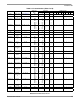
TBA Transfer B to A B ⇒ A INH 17 — 2 ———— ∆∆0—
TEST TEST (Only in
Test Modes)
Address Bus Counts INH 00 — * — — — — — — — —
TPA Transfer CC
Register to A
CCR ⇒ A INH 07 — 2 ————————
TST (opr) Test for Zero or
Minus
M – 0 EXT
IND,X
IND,Y
7D
6D
18 6D
hh ll
ff
ff
6
6
7
———— ∆∆00
TSTA Test A for Zero
or Minus
A – 0 A INH 4D — 2 — — — — ∆∆00
TSTB Test B for Zero
or Minus
B – 0 B INH 5D — 2 — — — — ∆∆00
TSX Transfer Stack
Pointer to X
SP + 1 ⇒ IX INH 30 — 3 ————————
TSY Transfer Stack
Pointer to Y
SP + 1 ⇒ IY INH 18 30 — 4 ————————
TXS Transfer X to
Stack Pointer
IX – 1 ⇒ SP INH 35 — 3 ————————
TYS Transfer Y to
Stack Pointer
IY – 1 ⇒ SP INH 18 35 — 4 ————————
WAI Wait for
Interrupt
Stack Regs & WAIT INH 3E — ** — — — — — — — —
XGDX Exchange D
with X
IX ⇒ D, D ⇒ IX INH 8F — 3 ————————
XGDY Exchange D
with Y
IY ⇒ D, D ⇒ IY INH 18 8F — 4 ————————
Cycle
* Infinity or until reset occurs
** 12 cycles are used beginning with the opcode fetch. A wait state is entered which remains in effect for an integer number of MPU E-clock
cycles (n) until an interrupt is recognized. Finally, two additional cycles are used to fetch the appropriate interrupt vector (14 + n total).
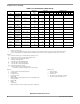
Operands
dd = 8-bit direct address ($0000–$00FF) (high byte assumed to be $00)
ff = 8-bit positive offset $00 (0) to $FF (255) (is added to index)
hh = High-order byte of 16-bit extended address
ii = One byte of immediate data
jj = High-order byte of 16-bit immediate data
kk = Low-order byte of 16-bit immediate data
ll = Low-order byte of 16-bit extended address
mm = 8-bit mask (set bits to be affected)
rr = Signed relative offset $80 (–128) to $7F (+127)
(offset relative to address following machine code offset byte)
Operators
( ) Contents of register shown inside parentheses
⇐ Is transferred to
⇑ Is pulled from stack
⇓
Is pushed onto stack
• Boolean AND
+ Arithmetic addition symbol except where used as inclusive-OR symbol
in Boolean formula
⊕ Exclusive-OR
∗ Multiply
: Concatenation
– Arithmetic subtraction symbol or negation symbol (two’s complement)
Condition Codes
— Bit not changed
0 Bit always cleared
1 Bit always set
∆ Bit cleared or set, depending on operation
↓ Bit can be cleared, cannot become set
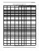
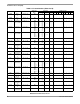
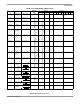
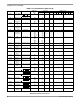
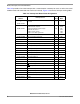
Table 3-2. Instruction Set (Sheet 8 of 8)
Mnemonic Operation Description
Addressing Instruction Condition Codes
Mode Opcode Operand Cycles S X H I N Z V C