MC68HC711D3 MC68HC11D3 MC68HC11D0 MC68L11D0 Data Sheet HC11 Microcontrollers MC68HC711D3 Rev. 2.1 07/2005 freescale.
MC68HC711D3 Data Sheet To provide the most up-to-date information, the revision of our documents on the World Wide Web will be the most current. Your printed copy may be an earlier revision. To verify you have the latest information available, refer to: http://www.freescale.com Freescale™ and the Freescale logo are trademarks of Freescale Semiconductor, Inc. © Freescale Semiconductor, Inc., 2005. All rights reserved. MC68HC711D3 Data Sheet, Rev. 2.
Revision History The following revision history table summarizes changes contained in this document. For your convenience, the page number designators have been linked to the appropriate location. Revision History Date Revision Level Page Number(s) Description Reformatted to current publications standards N/A Removed references to PROG mode. September, 2003 2 Corrected pin assignments for: Figure 1-2. Pin Assignments for 40-Pin Plastic DIP Figure 1-3.
List of Chapters Chapter 1 General Description. . . . . . . . . . . . . . . . . . . . . . . . . . . . . . . . . . . . . . . . . . . . . . . . 13 Chapter 2 Operating Modes and Memory . . . . . . . . . . . . . . . . . . . . . . . . . . . . . . . . . . . . . . . 21 Chapter 3 Central Processor Unit (CPU). . . . . . . . . . . . . . . . . . . . . . . . . . . . . . . . . . . . . . . . 33 Chapter 4 Resets, Interrupts, and Low-Power Modes . . . . . . . . . . . . . . . . . . . . . . . . . . . . .
List of Chapters MC68HC711D3 Data Sheet, Rev. 2.
Table of Contents Chapter 1 General Description 1.1 1.2 1.3 1.4 1.5 1.6 1.7 1.8 1.9 1.10 1.11 1.12 1.13 1.14 Introduction . . . . . . . . . . . . . . . . . . . . . . . . . . . . . . . . . . . . . . . . . . . . . . . . . . . . . . . . . . . . . . . . Features. . . . . . . . . . . . . . . . . . . . . . . . . . . . . . . . . . . . . . . . . . . . . . . . . . . . . . . . . . . . . . . . . . . Structure . . . . . . . . . . . . . . . . . . . . . . . . . . . . . . . . . . . . . . . . . . . . . . . . . . . . . . .
Table of Contents Chapter 3 Central Processor Unit (CPU) 3.1 Introduction . . . . . . . . . . . . . . . . . . . . . . . . . . . . . . . . . . . . . . . . . . . . . . . . . . . . . . . . . . . . . . . . 3.2 CPU Registers . . . . . . . . . . . . . . . . . . . . . . . . . . . . . . . . . . . . . . . . . . . . . . . . . . . . . . . . . . . . . . 3.2.1 Accumulators A, B, and D . . . . . . . . . . . . . . . . . . . . . . . . . . . . . . . . . . . . . . . . . . . . . . . . . . 3.2.2 Index Register X (IX) . . . .
4.4 4.4.1 4.4.2 Low-Power Operation . . . . . . . . . . . . . . . . . . . . . . . . . . . . . . . . . . . . . . . . . . . . . . . . . . . . . . . . 60 Stop Mode . . . . . . . . . . . . . . . . . . . . . . . . . . . . . . . . . . . . . . . . . . . . . . . . . . . . . . . . . . . . . . 60 Wait Mode . . . . . . . . . . . . . . . . . . . . . . . . . . . . . . . . . . . . . . . . . . . . . . . . . . . . . . . . . . . . . . 60 Chapter 5 Input/Output (I/O) Ports 5.1 5.2 5.3 5.3.1 5.3.2 5.4 5.4.1 5.4.2 5.4.3 5.
Table of Contents 7.5.3 7.5.4 7.6 7.7 7.7.1 7.7.2 7.7.3 Serial Clock (SCK) . . . . . . . . . . . . . . . . . . . . . . . . . . . . . . . . . . . . . . . . . . . . . . . . . . . . . . . . Slave Select (SS) . . . . . . . . . . . . . . . . . . . . . . . . . . . . . . . . . . . . . . . . . . . . . . . . . . . . . . . . . SPI System Errors . . . . . . . . . . . . . . . . . . . . . . . . . . . . . . . . . . . . . . . . . . . . . . . . . . . . . . . . . . . SPI Registers . . . . . . . . . . . . . . . . . . . . .
9.8 9.9 Expansion Bus Timing . . . . . . . . . . . . . . . . . . . . . . . . . . . . . . . . . . . . . . . . . . . . . . . . . . . . . . . 115 Serial Peripheral Interface Timing . . . . . . . . . . . . . . . . . . . . . . . . . . . . . . . . . . . . . . . . . . . . . . 117 Chapter 10 Ordering Information and Mechanical Specifications 10.1 10.2 10.3 10.4 10.5 Introduction . . . . . . . . . . . . . . . . . . . . . . . . . . . . . . . . . . . . . . . . . . . . . . . . . . . . . . . . . . . . . . .
Table of Contents MC68HC711D3 Data Sheet, Rev. 2.
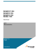
Chapter 1 General Description 1.1 Introduction This section depicts the general characteristics and features of the MC68HC711D3 high-density complementary metal-oxide semiconductor (HCMOS) microcontroller unit (MCU). The MC68HC711D3 contains highly sophisticated on-chip peripheral functions. This high-speed, low-power programmable read-only memory (PROM) MCU has a nominal bus speed of 3 MHz. The fully static design allows operations at frequencies down to dc.
General Description NOT BONDED IN 40-PIN PACKAGE MODA/LIR MODB/VSTBY RESET IRQ XIRQ/VPP XTAL EXTAL E OSCILLATOR MODE CONTROL PA7 PA6 PA5 PA4 PA3 PA2 PA1 PA0 CLOCK LOGIC INTERRUPT CONTROL 4 KBYTES EPROM OR OTPROM COP PAI/OC1 PULSE ACCUMULATOR OC2/OC1 OC3/OC1 OC4/OC1 TIMER IC4/OC5/OC1 IC1 IC2 IC3 PERIODIC INTERRUPT PORT A 192 BYTES STATIC RAM SS MC68HC711D3 CPU CORE VSS MOSI MISO VDD SERIAL COMMUNICATIONS INTERFACE (SCI) SCK SERIAL PERIPHERAL INTERFACE (SPI) TxD RxD EVSS MULTIPLEXED A
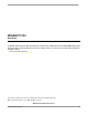
Pin Descriptions VSS 1 40 XTAL PC0 2 39 EXTAL PC1 3 38 E PC2 4 37 MODA/LIR PC3 5 36 MODB/VSTBY PC4 6 35 PB0 PC5 7 34 PB1 PC6 8 33 PB2 PC7 9 32 PB3 XIRQ/VPP 10 31 PB4 PD7/R/W 11 30 PB5 PD6/AS 12 29 PB6 RESET 13 28 PB7 IRQ 14 27 PA0 PD0 15 26 PA1 PD1 16 25 PA2 PD2 17 24 PA3 PD3 18 23 PA5 PD4 19 22 PA7 PD5 20 21 VDD EXTAL E MODA/LIR MODB/VSTBY 42 41 40 VSS 2 XTAL PC0 3 43 PD1 4 EVSS PC2 5 44 PC3 6 Figure 1-2.
38 3 31 PB2 PC7 4 30 PB3 XIRQ 5 29 PB4 PD7 6 28 PB5 PD6 7 27 PB6 RESET 8 26 PB7 IRQ 9 25 NC 10 24 PA0 15 16 17 18 19 20 21 23 PA1 PD5 VDD PA7 PA6 PA5 PA4 PA3 PA2 MODB XTAL 39 PC6 14 MODA VSS 40 PB1 PD4 34 EVSS 41 32 13 35 PC0 42 2 12 E PC1 43 PB0 PD3 36 PC2 1 PC5 PD0 PD1 37 PC3 PC4 PD2 EXTAL General Description Figure 1-4. Pin Assignments for 44-Pin QFP 1.
Interrupt Request (IRQ) MCU 4xE CMOS-COMPATIBLE EXTERNAL OSCILLATOR EXTAL XTAL NC OR 10K–100K LOAD FIRST MCU SECOND MCU 25 pF * EXTAL EXTAL 10 M 4xE CRYSTAL 25 pF * XTAL NC OR 10K–100K LOAD XTAL MCU 25 pF * EXTAL 10 M 4xE CRYSTAL 25 pF * XTAL * Values includes all stray capacitances. Figure 1-5. Oscillator Connections 1.9 Interrupt Request (IRQ) The IRQ input provides a means of applying asynchronous interrupt requests to the microcontroller unit (MCU).
General Description 1.10 Non-Maskable Interrupt/Programming Voltage (XIRQ/VPP) The XIRQ input provides the capability for asynchronously applying non-maskable interrupts to the MCU after a power-on reset (POR). During reset, the X bit in the condition code register (CCR) is set masking any interrupt until enabled by software. This level-sensitive input requires an external pullup resistor to VDD.
Input/Output Lines (PA7–PA0, PB7–PB0, PC7–PC0, and PD7–PD0) Refer to Table 1-1 for details about the functions of the 32 port signals within different operating modes. Table 1-1.
General Description MC68HC711D3 Data Sheet, Rev. 2.
Chapter 2 Operating Modes and Memory 2.1 Introduction This section contains information about: • The modes that define MC68HC711D3 operating conditions • The on-chip memory that allows the microcontroller unit (MCU) to be configured for various applications • The 4-Kbytes of programmable read-only memory (PROM) 2.2 Operating Modes The MC68HC711D3 uses two dedicated pins, MODA and MODB, to select one of two normal operating modes or one of two special operating modes.
Operating Modes and Memory If this mode is entered out of reset, the EPROM is located at $7000–$7FFF and vector accesses are from external memory. To be in expanded-multiplexed mode with EPROM located at $F000–$FFFF, it is necessary to start in single-chip mode, executing out of EPROM, and then set the MDA bit of the HPRIO register to switch mode. NOTE R/W, AS, and the high-order address bus (port B) are inputs in single-chip mode.
Memory Map Table 2-2. Bootstrap Mode Jump Vectors (Continued) Address Vector 00EB Real-time interrupt 00EE IRQ 00F1 XIRQ 00F4 SWI 00F7 Illegal opcode 00FA COP fail 00FD Clock monitor BF00 (Boot) Reset 2.2.4 Special Test Mode This special expanded mode is primarily intended or production testing. The user can access a number of special test control bits in this mode. Reset and interrupt vectors are fetched externally from locations $BFC0–$BFFF.
Operating Modes and Memory $0000 $0000 INTERNAL REGISTERS AND I/O (MAY BE MAPPED TO ANY 4-K BOUNDARY $003F USING INIT REGISTER) $1000 $2000 $0040 192 BYTES STATIC RAM (MAY BE MAPPED TO ANY 4-K BOUNDARY $00FF USING THE INIT REGISTER) $3000 $4000 $5000 $7000 4 KBYTES PROM (ROM) PRESENT AT RESET AND MAY BE DISABLED BY $7FFF EPON (ROM ON) BIT IN CONFIG REGISTER. INTERRUPT VECTORS ARE EXTERNAL.
Memory Map Addr. $0000 Register Name Port A Data Register Read: (PORTA) Write: See page 61. Reset: $0001 Reserved $0002 Port C Control Register Read: (PIOC) Write: See page 63. Reset: $0003 Port C Data Register Read: (PORTC) Write: See page 63. Reset: $0004 Port B Data Register Read: (PORTB) Write: See page 62. Reset: $0005 $0006 $0007 $0008 $0009 Reserved Data Direction Register Read: for Port B (DDRB) Write: See page 62.
Operating Modes and Memory Addr. Bit 7 6 5 4 3 2 1 Bit 0 Bit 15 Bit 14 Bit 13 Bit 12 Bit 11 Bit 10 Bit 9 Bit 8 0 0 0 0 0 0 0 0 Bit 7 Bit 6 Bit 5 Bit 4 Bit 3 Bit 2 Bit 1 Bit 0 0 0 0 0 0 0 0 0 Timer Input Capture Register 1 Read: High (TIC1) Write: See page 89. Reset: Bit 15 Bit 14 Bit 13 Bit 12 Bit 11 Bit 10 Bit 9 Bit 8 Bit 7 Bit 6 Bit 5 Bit 2 Bit 1 Bit 0 $0011 Timer Input Capture Register 1 Read: Low (TIC1) Write: See page 89.
Memory Map Addr.
Operating Modes and Memory Addr. $0026 $0027 $0028 Register Name Pulse Accumulator Control Read: Register (PACTL) Write: See pages 99 and 102. Reset: Pulse Accumulator Count Register Read: (PACNT) Write: See page 103. Reset: SPI Control Register Read: (SPCR) Write: See page 81. Reset: $0029 SPI Status Register Read: (SPSR) Write: See page 82. Reset: $002A SPI Data I/O Register Read: (SPDR) Write: See page 83. Reset: $002B $002C Baud Rate Register Read: (BAUD) Write: See page 72.
Memory Map Addr. $003A $003B $003C Register Name Arm/Reset COP Timer Circuitry Read: Register (COPRST) Write: See page 48. Reset: PROM Programming Control Read: Register (PPROG) Write: See page 32. Reset: Highest Priority I-Bit Interrupt and Read: Miscellaneous Register (HPRIO) Write: See page 58.
Operating Modes and Memory RAM2–RAM0 (INIT bits 7–4) specify the starting address for the 192 bytes of static RAM. REG3–REG0 (INIT bits 3–0) specify the starting address for the control and status register block. In each case, the four RAM or REG bits become the four upper bits of the 16-bit address of the RAM or register. Since the INIT register is set to $00 by reset, the internal registers begin at $0000 and RAM begins at $0040.
Programmable Read-Only Memory (PROM) ROMON — PROM Enable Bit This bit is set out of reset, enabling the EPROM or OTPROM in all modes. This bit is writable once in normal modes (SMOD = 0), but is writable at any time in special modes (SMOD = 1). 1 = PROM is present in the memory map. 0 = PROM is disabled from the memory map. NOTE In expanded mode out of reset, the EPROM or OTPROM is located at $7000–$7FFF. In all other modes, the PROM resides at $F000–$FFFF. 2.
Operating Modes and Memory 2.4.2 Programming the EPROM with Downloaded Data When using this method, the EPROM is programmed by software while in the special test or bootstrap modes. User-developed software can be uploaded through the SCI or a ROM-resident EPROM programming utility can be used. The 12-volt nominal programming voltage must be present on the XIRQ/VPP pin. To use the resident utility, bootload a 3-byte program consisting of a single jump instruction to $BF00.
Chapter 3 Central Processor Unit (CPU) 3.1 Introduction This section presents information on M68HC11 central processor unit (CPU): • Architecture • Data types • Addressing modes • Instruction set • Special operations such as subroutine calls and interrupts The CPU is designed to treat all peripheral, input/output (I/O), and memory locations identically as addresses in the 64-Kbyte memory map. This is referred to as memory-mapped I/O. I/O has no instructions separate from those used by memory.
Central Processor Unit (CPU) 3.2.1 Accumulators A, B, and D Accumulators A and B are general-purpose 8-bit registers that hold operands and results of arithmetic calculations or data manipulations. For some instructions, these two accumulators are treated as a single double-byte (16-bit) accumulator called accumulator D.
CPU Registers JSR, JUMP TO SUBROUTINE MAIN PROGRAM $9D = JSR PC DIRECT RTN PC RTI, RETURN FROM INTERRUPT INTERRUPT PROGRAM $3B = RTI PC dd SP+1 CONDITION CODE NEXT MAIN INSTR SP+2 ACMLTR B MAIN PROGRAM $AD = JSR SP+3 INDXD,X ACMLTR A SP+4 INDEX REGISTER (XH) SP+5 INDEX REGISTER (XL) ff RTN NEXT MAIN INSTR PC MAIN PROGRAM $18 = PRE $AD = JSR INDXD,Y STACK SP+6 INDEX REGISTER (YH) SP-2 SP-1 RTNL SP+7 INDEX REGISTER (YL) RTNL SP+8 SP RTNH SP+9 PC NEXT MAIN INSTR PC MAIN PROGRAM $BD
Central Processor Unit (CPU) At the end of the interrupt service routine, a return-from interrupt (RTI) instruction is executed. The RTI instruction causes the saved registers to be pulled off the stack in reverse order. Program execution resumes at the return address. Certain instructions push and pull the A and B accumulators and the X and Y index registers and are often used to preserve program context.
Data Types 3.2.6.4 Negative (N) The N bit is set if the result of an arithmetic, logic, or data manipulation operation is negative (MSB = 1). Otherwise, the N bit is cleared. A result is said to be negative if its most significant bit (MSB) is a 1. A quick way to test whether the contents of a memory location has the MSB set is to load it into an accumulator and then check the status of the N bit. 3.2.6.
Central Processor Unit (CPU) A byte is eight bits wide and can be accessed at any byte location. A word is composed of two consecutive bytes with the most significant byte at the lower value address. Because the M68HC11 is an 8-bit CPU, there are no special requirements for alignment of instructions or operands. 3.4 Opcodes and Operands The M68HC11 Family of microcontrollers uses 8-bit opcodes. Each opcode identifies a particular instruction and associated addressing mode to the CPU.
Instruction Set 3.5.3 Extended In the extended addressing mode, the effective address of the argument is contained in two bytes following the opcode byte. These are 3-byte instructions (or 4-byte instructions if a prebyte is required). One or two bytes are needed for the opcode and two for the effective address. 3.5.4 Indexed In the indexed addressing mode, an 8-bit unsigned offset contained in the instruction is added to the value contained in an index register (IX or IY).
Central Processor Unit (CPU) Table 3-2.
Instruction Set Table 3-2.
Central Processor Unit (CPU) Table 3-2.
Instruction Set Table 3-2.
Central Processor Unit (CPU) Table 3-2.
Instruction Set Table 3-2.
Central Processor Unit (CPU) Table 3-2.
Chapter 4 Resets, Interrupts, and Low-Power Modes 4.1 Introduction This section describes the internal and external resets and interrupts of the MC68HC711D3 and its two low power-consumption modes. 4.2 Resets The microcontroller unit (MCU) can be reset in any of these four ways: 1. An active-low input to the RESET pin 2. A power-on reset (POR) function 3. A clock monitor failure 4.
Resets, Interrupts, and Low-Power Modes The sequence for resetting the watchdog timer is: 1. Write $55 to the COP reset register (COPRST) to arm the COP timer clearing mechanism. 2. Write $AA to the COPRST register to clear the COP timer Both writes must occur in this sequence prior to the timeout, but any number of instructions can be executed between the two writes. Table 4-1. COP Time Out Periods E ÷ 215 CR0 CR1 Divided By XTAL = 223 Time Out –0/+15.6 ms XTAL = 8.0 MHz Time Out –0/+16.4 ms XTAL = 4.
Interrupts Address: Read: Write: Reset: $0039 Bit 7 6 5 4 3 2 1 Bit 0 0 0 IRQE DLY CME 0 CR1 CR0 0 0 0 1 0 0 0 0 Figure 4-2. System Configuration Options Register (OPTION) Bits 7, 6, and 2 — Not implemented Always read 0. IRQE — IRQ Edge/Level Sensitivity Select This bit can be written only once during the first 64 E-clock cycles after reset in normal modes. 1 = IRQ is configured to respond only to falling edges. 0 = IRQ is configured for low-level wired-OR operation.
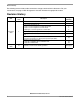
Resets, Interrupts, and Low-Power Modes Table 4-2 provides a list of the interrupts with a vector location in memory for each, as well as the actual condition code and control bits that mask each interrupt. Figure 4-3 shows the interrupt stacking order. Table 4-2.
Interrupts STACK SP PCL SP – 1 PCH SP – 2 IYL SP – 3 IYH SP – 4 IXL SP – 5 IXH SP – 6 ACCA SP – 7 ACCB SP – 8 CCR SP – 9 — SP BEFORE INTERRUPT — SP AFTER INTERRUPT Figure 4-3. Interrupt Stacking Order 4.3.1 Software Interrupt (SWI) The SWI is executed the same as any other instruction and takes precedence over interrupts only if the other interrupts are masked (with I and X bits in the CCR set).
Resets, Interrupts, and Low-Power Modes When an I bit related interrupt occurs, the I bit is automatically set by hardware after stacking the CCR byte. The X bit is not affected. When an X bit related interrupt occurs, both the X and the I bit are automatically set by hardware after stacking the CCR. A return-from-interrupt (RTI) instruction restores the X and I bits to their preinterrupt request state. 4.3.
Interrupts HIGHEST PRIORITY POWER-ON RESET (POR) DELAY 4064 E CYCLES EXTERNAL RESET CLOCK MONITOR FAIL (WITH CME = 1) LOWEST PRIORITY COP WATCHDOG TIMEOUT (WITH NOCOP = 0) LOAD PROGRAM COUNTER WITH CONTENTS OF $FFFE, $FFFF (VECTOR FETCH) LOAD PROGRAM COUNTER WITH CONTENTS OF $FFFC, $FFFD (VECTOR FETCH) LOAD PROGRAM COUNTER WITH CONTENTS OF $FFFA, $FFFB (VECTOR FETCH) SET BITS S, I, AND X RESET MCU HARDWARE 1A BEGIN INSTRUCTION SEQUENCE Y BIT X IN CCR = 1? N XIRQ PIN LOW? Y N 2A STACK CPU REGISTE
Resets, Interrupts, and Low-Power Modes 2A Y I BIT IN CCR SET? N ANY I-BIT INTERRUPT PENDING? Y STACK CPU REGISTERS N FETCH OPCODE N STACK CPU REGISTERS ILLEGAL OPCODE? Y SET I BIT WAI Y INSTRUCTION? FETCH VECTOR $FFF8, $FFF9 STACK CPU REGISTERS N Y STACK CPU REGISTERS SWI INSTRUCTION? N Y RTI INSTRUCTION? N RESTORE CPU REGISTERS FROM STACK EXECUTE THIS INSTRUCTION 1A INTERRUPT YET? Y SET I BIT FETCH VECTOR $FFF6, $FFF7 N SET I BIT RESOLVE INTERRUPT PRIORITY AND FETCH VECTOR FOR HIG
Interrupts BEGIN X BIT IN CCR SET ? Y N XIRQ PIN LOW ? Y FETCH VECTOR $FFF4, $FFF5 N HIGHEST PRIORITY INTERRUPT ? N IRQ ? SET X BIT Y FETCH VECTOR Y FETCH VECTOR $FFF2, $FFF3 N RTII = 1 ? Y N REAL-TIME INTERRUPT ? Y FETCH VECTOR $FFF0, $FFF1 Y FETCH VECTOR $FFEE, $FFEF Y FETCH VECTOR $FFEC, $FFED Y FETCH VECTOR $FFEA, $FFEB Y FETCH VECTOR $FFE8, $FFE9 N Y IC1I = 1 ? N TIMER IC1F ? N Y IC2I = 1 ? N TIMER IC2F ? N Y IC3I = 1 ? N TIMER IC3F ? N Y OC1I = 1 ? N TIMER OC1F ?
Resets, Interrupts, and Low-Power Modes 2A 2B Y OC2I = 1? Y FETCH VECTOR $FFE6, $FFE7 Y FETCH VECTOR $FFE4, $FFE5 Y FETCH VECTOR $FFE2, $FFE3 Y FETCH VECTOR $FFE0, $FFE1 Y FETCH VECTOR $FFDE, $FFDF Y FETCH VECTOR $FFDC, $FFDD Y FETCH VECTOR $FFDA, $FFDB Y FETCH VECTOR $FFD8, $FFD9 N N OC3I = 1? Y FLAG OC3F = 1 N N OC4I = 1? Y FLAG OC4F = 1? N N OC5I = 1? Y FLAG OC5F = 1? N N Y TOI = 1? FLAG TOF = 1? N N PAOVI = 1? Y FLAG PAOVF = 1 N N PAII = 1? Y FLAG PAIF = 1? N N
Interrupts BEGIN FLAG RDRF = 1? Y N OR = 1? Y Y RE = 1? TIE = 1? Y TE = 1? Y N Y TCIE = 1? Y N N IDLE = 1? Y N N N TC = 1? Y N N TDRE = 1? RIE = 1? Y Y ILIE = 1? RE = 1? N N NO VALID SCI REQUEST Y N YES VALID SCI REQUEST Figure 4-6. Interrupt Source Resolution within SCI MC68HC711D3 Data Sheet, Rev. 2.
Resets, Interrupts, and Low-Power Modes 4.3.6 Highest Priority I Interrupt and Miscellaneous Register (HPRIO) Four bits of this register (PSEL3–PSEL0) are used to select one of the I bit related interrupt sources and to elevate it to the highest I bit masked position of the priority resolution circuit. In addition, four miscellaneous system control bits are included in this register.
Interrupts IRVNE E Clock IRV IRVNE IRVNE Out Out Out Affects May of Reset of Reset of Reset Only be Written Mode Single chip 0 On Off E Once Expanded multiplexed 0 On Off IRV Once Bootstrap 0 On Off E Once Special test 1 On On IRV Once NOTE To prevent bus conflicts, when using internal read visibility, the user must disable all external devices from driving the data bus during any internal access.
Resets, Interrupts, and Low-Power Modes 4.4 Low-Power Operation The M68HC11 Family of microcontroller units (MCU) has two programmable low power-consumption modes: stop and wait. In the wait mode, the on-chip oscillator remains active. In the stop mode, the oscillator is stopped. This subsection describes these two low power-consumption modes. 4.4.1 Stop Mode The STOP instruction places the MCU in its lowest power-consumption mode, provided the S bit in the CCR is cleared.
Chapter 5 Input/Output (I/O) Ports 5.1 Introduction The MC68HC711D3 has four 8-bit input/output (I/O) ports; A, B, C, and D. In the 40-pin version, port A bits 4 and 6 are not bonded. Port functions are controlled by the particular mode of operation selected, as shown in Table 1-1. Port Signal Functions. In the single-chip and bootstrap modes, all the ports are configured as parallel input/output (I/O) data ports.
Input/Output (I/O) Ports PORTA can be read any time. Inputs return the pin level, whereas outputs return the pin driver input level. If written, PORTA stores the data in an internal latch. It drives the pins only if they are configured as outputs. Writes to PORTA do not change the pin state when the pins are configured for timer output compares. Out of reset, port A bits 7 and 3–0 are general high-impedance inputs, while bits 6–4 are outputs, driving low.
Port C 5.4 Port C Port C is an 8-bit, general-purpose I/O port with a data register (PORTC) and a data direction register (DDRC). In the single-chip mode, port C pins are general-purpose I/O pins (PC7–PC0). In the expanded-multiplexed mode, port C pins are configured as multiplexed address/data pins. During the address cycle, bits 7–0 of the address are output on PC7–PC0. During the data cycle, bits 7–0 (PC7–PC0) are bidirectional data pins controlled by the R/W signal. 5.4.
Input/Output (I/O) Ports 5.5 Port D Port D is an 8-bit, general-purpose I/O port with a data register (PORTD) and a data direction register (DDRD). The eight port D bits (D7–D0) can be used for general-purpose I/O, for the serial communications interface (SCI) and serial peripheral interface (SPI) subsystems, or for bus data direction control 5.5.
Chapter 6 Serial Communications Interface (SCI) 6.1 Introduction The serial communications interface (SCI) is a universal asynchronous receiver transmitter (UART), one of two independent serial input/output (I/O) subsystems in the MC68HC711D3. It has a standard non-return to zero (NRZ) format (one start, eight or nine data, and one stop bit). Several baud rates are available. The SCI transmitter and receiver are independent, but use the same data format and bit rate. 6.
Serial Communications Interface (SCI) TRANSMITTER BAUD RATE CLOCK (WRITE ONLY) SCDR Tx BUFFER DDD1 10 (11) - BIT Tx SHIFT REGISTER 2 1 0 PIN BUFFER AND CONTROL L PD1 TxD BREAK—JAM 0s 3 JAM ENABLE 4 PREAMBLE—JAM 1s 5 SHIFT ENABLE 6 TRANSFER Tx BUFFER SIZE 8/9 H (8) 7 FORCE PIN DIRECTION (OUT) SCCR1 SCI CONTROL 1 FE NF OR IDLE TC RDRF TDRE WAKE M T8 R8 TRANSMITTER CONTROL LOGIC SCSR INTERRUPT STATUS TDRE TIE TC SBK RWU RE TE ILIE RIE TCIE TIE TCIE SCCR2 SCI CONTROL 2
Receive Operation 16X BAUD RATE CLOCK PIN BUFFER AND CONTROL PD0 RxD 10 (11) - BIT Rx SHIFT REGISTER STOP ÷16 DATA RECOVERY START DDD0 (8) 7 6 5 4 3 MSB DISABLE DRIVER 2 1 0 ALL 1s RE M FE NF OR IDLE RDRF TDRE TC RWU WAKE M T8 R8 WAKEUP LOGIC SCDR Rx BUFFER SCSR SCI STATUS 1 SCCR1 SCI CONTROL 1 (READ ONLY) RDRF RIE IDLE ILIE OR SBK RWU RE TE ILIE RIE TCIE TIE RIE SCCR2 SCI CONTROL 2 SCI Tx REQUESTS SCI INTERRUPT REQUEST INTERNAL DATA BUS Figure 6-2.
Serial Communications Interface (SCI) 6.5 Wakeup Feature The wakeup feature reduces SCI service overhead in multiple receiver systems. Software for each receiver evaluates the first character of each message. The receiver is placed in wakeup mode by writing a 1 to the RWU bit in the SCCR2 register. While RWU is 1, all of the receiver-related status flags (RDRF, IDLE, OR, NF, and FE) are inhibited (cannot become set). Although RWU can be cleared by a software write to SCCR2, to do so would be unusual.
SCI Error Detection 6.6 SCI Error Detection Three error conditions can occur during generation of SCI system interrupts: • Serial communications data register (SCDR) overrun • Received bit noise • Framing Three bits (OR, NF, and FE) in the serial communications status register (SCSR) indicate if one of these error conditions exists. The overrun error (OR) bit is set when the next byte is ready to be transferred from the receive shift register to the SCDR and the SCDR is already full (RDRF bit is set).
Serial Communications Interface (SCI) 6.7.2 SCI Control Register 1 The SCI control register 1 (SCCR1) provides the control bits that determine word length and select the method used for the wakeup feature. Address: Read: Write: Reset: $002C Bit 7 6 5 4 3 2 1 Bit 0 R8 T8 0 M WAKE 0 0 0 U U 0 0 0 0 0 0 U = Unaffected Figure 6-4. SCI Control Register 1 (SCCR1) R8 — Receive Data Bit 8 If M bit is set, R8 stores the ninth bit in the receive data character.
SCI Registers ILIE — Idle Line Interrupt Enable Bit 1 = IDLE interrupts disabled 1 = SCI interrupt requested when IDLE status flag is set TE — Transmitter Enable Bit When TE goes from 0 to 1, one unit of idle character time (logic 1) is queued as a preamble.
Serial Communications Interface (SCI) IDLE — Idle Line Detected Flag This flag is set if the RxD line is idle. Once cleared, IDLE is not set again until the RxD line has been active and becomes idle again. The IDLE flag is inhibited when RWU = 1. Clear IDLE by reading SCSR with IDLE set and then reading SCDR. 0 = RxD line active 1 = RxD line idle OR — Overrun Error Flag OR is set if a new character is received before a previously received character is read from SCDR.
SCI Registers SCP1 and SCP0 — SCI Baud Rate Prescaler Select Bits These two bits select a prescale factor for the SCI baud rate generator that determines the highest possible baud rate. Table 6-1. Baud Rate Prescale Selects Crystal Frequency in MHz SCP1 and SCP0 Divide Internal Clock By 4.0 MHz (Baud) 8.0 MHz (Baud) 10.0 MHz (Baud) 12.0 MHz (Baud) 00 1 62.50 K 125.0 K 156.25 K 187.5 K 01 3 20.83 K 41.67 K 52.08 K 62.5 K 10 4 15.625 K 31.25 K 38.4 K 46.88 K 11 13 4800 9600 12.
Serial Communications Interface (SCI) EXTAL XTAL INTERNAL BUS CLOCK (PH2) OSCILLATOR AND CLOCK GENERATOR ÷3 (÷ 4) ÷4 ÷ 13 SCP1 AND SCP0 0:0 E 0:1 1:0 1:1 AS SCR2–SCR0 0:0:0 ÷2 0:0:1 ÷2 0:1:0 ÷2 0:1:1 ÷ 16 ÷2 1:0:0 ÷2 1:0:1 ÷2 1:1:0 ÷2 1:1:1 SCI TRANSMIT BAUD RATE (1X) SCI RECEIVE BAUD RATE (16X) Figure 6-8. SCI Baud Rate Diagram MC68HC711D3 Data Sheet, Rev. 2.
Status Flags and Interrupts 6.8 Status Flags and Interrupts The SCI transmitter has two status flags. These status flags can be read by software (polled) to tell when the corresponding condition exists. Alternatively, a local interrupt enable bit can be set to enable each of these status conditions to generate interrupt requests when the corresponding condition is present.
Serial Communications Interface (SCI) BEGIN FLAG RDRF = 1? Y N OR = 1? Y Y Y TIE = 1? TCIE = 1? Y N Y TE = 1? Y N Y N N IDLE = 1? RE = 1? N N TC = 1? Y N N TDRE = 1? RIE = 1? Y Y ILIE = 1? RE = 1? N N NO VALID SCI REQUEST Y N VALID SCI REQUEST Figure 6-9. Interrupt Source Resolution within SCI MC68HC711D3 Data Sheet, Rev. 2.
Chapter 7 Serial Peripheral Interface (SPI) 7.1 Introduction The serial peripheral interface (SPI), an independent serial communications subsystem, allows the microcontroller unit (MCU) to communicate synchronously with peripheral devices, such as: • Transistor-transistor logic (TTL) shift registers • Liquid crystal diode (LCD) display drivers • Analog-to-digital converter (ADC) subsystems • Other microprocessors (MCUs) The SPI is also capable of inter-processor communication in a multiple master system.
Serial Peripheral Interface (SPI) PH2 (INTERNAL) MISO PD2 S M S M LSB 8-BIT SHIFT REGISTER READ DATA BUFFER CLOCK M CLOCK LOGIC SCK PD4 S SPR0 DWOM SS PD5 MSTR SPR1 SELECT SPI CLOCK (MASTER) MOSI PD3 PIN CONTROL LOGIC MSB DIVIDER ÷4 ÷16 ÷32 SPE ÷2 MSTR SPR0 SPR1 CPOL CPHA MSTR DWOM SPIE MODF WCOL SPIF SPI STATUS REGISTER SPE SPE SPI CONTROL SPI CONTROL REGISTER 8 SPI INTERRUPT REQUEST INTERNAL DATA BUS Figure 7-1. SPI Block Diagram MC68HC711D3 Data Sheet, Rev. 2.
Clock Phase and Polarity Controls SCK CYCLE # 1 2 3 4 5 6 7 8 SCK (CPOL = 0) SCK (CPOL = 1) SAMPLE INPUT MSB (CPHA = 0) DATA OUT 6 5 4 3 2 1 LSB SAMPLE INPUT MSB (CPHA = 1) DATA OUT 6 5 4 3 2 1 LSB SS (TO SLAVE) SLAVE CPHA=1 TRANSFER IN PROGRESS 3 1. SS ASSERTED 2. MASTER WRITES TO SPDR 3. FIRST SCK EDGE 4. SPIF SET 5. SS NEGATED MASTER TRANSFER IN PROGRESS 2 4 SLAVE CPHA=0 TRANSFER IN PROGRESS 1 5 Figure 7-2. SPI Transfer Format 7.
Serial Peripheral Interface (SPI) 7.5.2 Master Out/Slave In (MOSI) The MOSI line is the second of the two unidirectional serial data signals. It is an output from a master device and an input to a slave device. The master device places data on the MOSI line a half-cycle before the clock edge that the slave device uses to latch the data. 7.5.
SPI Registers A write collision error occurs if the SPDR is written while a transfer is in progress. Because the SPDR is not double buffered in the transmit direction, writes to SPDR cause data to be written directly into the SPI shift register. Because this write corrupts any transfer in progress, a write collision error is generated. The transfer continues undisturbed, and the write data that caused the error is not written to the shifter.
Serial Peripheral Interface (SPI) CPOL — Clock Polarity Bit When the clock polarity bit is cleared and data is not being transferred, the SCK pin of the master device has a steady state low value. When CPOL is set, SCK idles high. Refer to Figure 7-2 and 7.4 Clock Phase and Polarity Controls. CPHA — Clock Phase Bit The clock phase bit, in conjunction with the CPOL bit, controls the clock-data relationship between master and slave. The CPHA bit selects one of two different clocking protocols.
SPI Registers Bits 3–0 — Not implemented Always reads 0 7.7.3 SPI Data I/O Register The SPI data I/O register (SPDR) is used when transmitting or receiving data on the serial bus. Only a write to this register initiates transmission or reception of a byte, and this only occurs in the master device. At the completion of transferring a byte of data, the SPIF status bit is set in both the master and slave devices. A read of the SPDR is actually a read of a buffer.
Serial Peripheral Interface (SPI) MC68HC711D3 Data Sheet, Rev. 2.
Chapter 8 Programmable Timer 8.1 Introduction The M68HC11 timing system is composed of five clock divider chains. The main clock divider chain includes a 16-bit free-running counter, which is driven by a programmable prescaler. The main timer's programmable prescaler provides one of the four clocking rates to drive the 16-bit counter. Two prescaler control bits select the prescale rate. The prescaler output divides the system clock by 1, 4, 8, or 16.
Programmable Timer OSCILLATOR AND CLOCK GENERATOR (DIVIDE BY FOUR) AS E CLOCK INTERNAL BUS CLOCK (PH2) PRESCALER (÷ 2, 4, 16, 32) SPR1 AND SPR0 SPI PRESCALER (÷ 1, 2, 4,....
Timer Structure Table 8-1. Timer Summary Control Bits 4.0 MHz 1.0 MHz 1000 ns PR1 and PR0 XTAL Frequencies 8.0 MHz 12.0 MHz 2.0 MHz 3.0 MHz 500 ns 333 ns Main Timer Count Rates Other Rates (E) (1/E) 00 1 count — overflow — 1.0 µs 65.536 ms 500 ns 32.768 ms 333 ns 21.845 ms (E/1) (E/216) 01 1 count — overflow — 4.0 µs 262.14 ms 2.0 µs 131.07 ms 1.333 µs 87.381 ms (E/4) (E/218) 10 1 count — overflow — 8.0 µs 524.29 ms 4.0 µs 262.14 ms 2.667 µs 174.
Programmable Timer MCU E CLOCK TCNT (HI) PRESCALER — DIVIDE BY 1, 4, 8, 16 PR1 16-BIT FREE RUNNING COUNTER PR0 TOI 16-BIT COMPARATOR = OC1F TOC1 (LO) 9 TOF TAPS FOR RTL, COP WATCHDOG, AND PULSE ACCUMULATOR 16-BIT TIMER BUS TOC1 (HI) TCNT (LO) FORCE OUTPUT COMPARE INTERRUPT REQUESTS (FURTHER QUALIFIED BY I BIT IN CCR) TO PULSE ACCUMULATOR OC1I FOC1 OC2I 16-BIT COMPARATOR = TOC2 (HI) TOC2 (LO) TOC3 (LO) OC5 16-BIT COMPARATOR = TI4/O5 (LO) I4/O5F CLK IC2I CLK BIT 3 PA3/IC4/ OC5/OC1
Input Capture 8.3.1 Timer Control 2 Register Use the control bits of timer control 2 register (TCTL2) to program input capture functions to detect a particular edge polarity on the corresponding timer input pin. Each of the input capture functions can be independently configured to detect rising edges only, falling edges only, any edge (rising or falling), or to disable the input capture function.
Programmable Timer Address: $0011 — TIC1 (Low) Bit 7 6 5 Read: Bit 7 Bit 6 Bit 5 Write: Reset: Address: $0012 — TIC2 (High) Bit 15 14 13 Read: Bit 15 Bit 14 Bit 13 Write: Reset: Address: $0013 — TIC2 (Low) Bit 7 6 5 Read: Bit 7 Bit 6 Bit 5 Write: Reset: Address: $0014 — TIC3 (High) Bit 15 14 13 Read: Bit 15 Bit 14 Bit 13 Write: Reset: Address: $0015 — TIC3 (Low) Bit 7 6 5 Read: Bit 7 Bit 6 Bit 5 Write: Reset: = Unimplemented 4 Bit 4 3 Bit 3 2 Bit 2 1 Bit 1 Bit 0 Bit 0 10 Bit 10 9 Bit 9 Bit 8 Bit 8
Output Compare (OC) 8.4 Output Compare (OC) Use the output compare (OC) function to program an action to occur at a specific time — when the 16-bit counter reaches a specified value. For each of the five output compare functions, there is a separate 16-bit compare register and a dedicated 16-bit comparator. The value in the compare register is compared to the value of the free-running counter on every bus cycle. When the compare register matches the counter value, an output compare status flag is set.
Programmable Timer Address: $0016 — TOC1 (High) Bit 15 14 Read: Bit 15 Bit 14 Write: Reset: 1 1 Address: $0017 — TOC1 (Low) Bit 7 6 Read: Bit 7 Bit 6 Write: Reset: 1 1 Address: Read: Write: Reset: $0018 — TOC2 (High) Bit 15 14 13 12 11 10 9 Bit 8 Bit 13 Bit 12 Bit 11 Bit 10 Bit 9 Bit 8 1 1 1 1 1 1 5 4 3 2 1 Bit 0 Bit 5 Bit 4 Bit 3 Bit 2 Bit 1 Bit 0 1 1 1 1 1 1 13 12 11 10 9 Bit 8 Bit 15 Bit 14 Bit 13 Bit 12 Bit 11 Bit 10 Bit 9 Bit 8 1 1 1 1 1 1 1 1
Output Compare (OC) 8.4.2 Timer Compare Force Register The timer compare force register (CFORC) allows forced early compares. FOC1–FOC5 correspond to the five output compares. These bits are set for each output compare that is to be forced. The action taken as a result of a forced compare is the same as if there were a match between the OCx register and the free-running counter, except that the corresponding interrupt status flag bits are not set.
Programmable Timer 8.4.4 Output Compare 1 Data Register Use this register with OC1 to specify the data that is to be stored on the affected pin of port A after a successful OC1 compare. When a successful OC1 compare occurs, a data bit in OC1D is stored in the corresponding bit of port A for each bit that is set in OC1M. Address: Read: Write: Reset: $000D Bit 7 6 5 4 3 2 1 Bit 0 OC1D7 OC1D6 OC1D5 OC1D4 OC1D3 0 0 0 0 0 0 0 0 0 0 0 Figure 8-9.
Output Compare (OC) 8.4.6 Timer Control 1 Register The bits of the timer control 1 register (TCTL1) specify the action taken as a result of a successful OCx compare. Address: Read: Write: Reset: $0020 Bit 7 6 5 4 3 2 1 Bit 0 OM2 OL2 OM3 OL3 OM4 OL4 OM5 OL5 0 0 0 0 0 0 0 0 Figure 8-11. Timer Control 1 Register (TCTL1) OM2–OM5 — Output Mode Bits OL2–OL5 — Output Level Bits These control bit pairs are encoded to specify the action taken after a successful OCx compare.
Programmable Timer 8.4.8 Timer Interrupt Flag 1 Register The timer interrupt flag 1 register (TFLG1) bits indicate when timer system events have occurred. Coupled with the bits of TMSK1, the bits of TFLG1 allow the timer subsystem to operate in either a polled or interrupt driven system. Each bit of TFLG1 corresponds to a bit in TMSK1 in the same position.
Output Compare (OC) PR1 and PR0 — Timer Prescaler Select Bits These bits are used to select the prescaler divide-by ratio. In normal modes, PR1 and PR0 can be written once only, and the write must be within 64 cycles after reset. Refer to Table 8-4 for specific timing values. Table 8-4. Timer Prescale PR1 and PR0 00 01 10 11 Prescaler 1 4 8 16 8.4.10 Timer Interrupt Flag 2 Register The timer interrupt flag 2 register (TFLG2) bits indicate when certain timer system events have occurred.
Programmable Timer 8.5 Real-Time Interrupt The real-time interrupt feature, used to generate hardware interrupts at a fixed periodic rate, is controlled and configured by two bits (RTR1 and RTR0) in the pulse accumulator control (PACTL) register. The RTII bit in the TMSK2 register enables the interrupt capability. The four different rates available are a product of the MCU oscillator frequency and the value of bits RTR1 and RTR0. Refer to Table 8-5 for the periodic real-time interrupt rates. Table 8-5.
Real-Time Interrupt PR1 and PR0 — Timer Prescaler Select Bits Refer to Table 8-4. NOTE Bits in TMSK2 correspond bit for bit with flag bits in TFLG2. Ones in TMSK2 enable the corresponding interrupt sources. 8.5.2 Timer Interrupt Flag 2 Register Bits of the timer interrupt flag 2 register (TFLG2) indicate the occurrence of timer system events. Coupled with the four high-order bits of TMSK2, the bits of TFLG2 allow the timer subsystem to operate in either a polled or interrupt driven system.
Programmable Timer DDRA7 — Data Direction Control for Port A Bit 7 Refer to 8.7 Pulse Accumulator. PAEN — Pulse Accumulator System Enable Bit Refer to 8.7 Pulse Accumulator. PAMOD — Pulse Accumulator Mode Bit Refer to 8.7 Pulse Accumulator. PEDGE — Pulse Accumulator Edge Control Bit Refer to 8.7 Pulse Accumulator. DDRA3 — Data Direction Register for Port A Bit 3 Refer to Chapter 5 Input/Output (I/O) Ports. I4/O5 — Input Capture 4/Output Compare 5 Bit Refer to 8.3 Input Capture.
Pulse Accumulator 1 INTERRUPT REQUESTS TMSK2 INT ENABLES PAIF PAOVF PAII PAOVI 2 TFLG2 INTERRUPT STATUS PAI EDGE DISABLE FLAG SETTING E ÷ 64 CLOCK (FROM MAIN TIMER) INPUT BUFFER AND EDGE DETECTION PA7/ PAI/OC1 PACNT 8-BIT COUNTER ENABLE OUTPUT BUFFER PEDGE PAMOD PAEN PAEN DDRA7 FROM MAIN TIMER OC1 OVERFLOW 2:1 MUX PACTL CONTROL INTERNAL DATA BUS Figure 8-19. Pulse Accumulator Table 8-7. Pulse Accumulator Timing in Gated Mode Common XTAL Frequencies Selected Crystal 4.0 MHz 8.
Programmable Timer 8.7.1 Pulse Accumulator Control Register Four of the pulse accumulator control register (PACTL) bits control an 8-bit pulse accumulator system. Another bit enables either the OC5 function or the IC4 function, while two other bits select the rate for the real-time interrupt system. Address: Read: Write: Reset: $0026 Bit 7 6 5 4 3 2 1 Bit 0 DDRA7 PAEN PAMOD PEDGE DDRA3 I4/O5 RTR1 RTR0 0 0 0 0 0 0 0 0 Figure 8-20.
Pulse Accumulator 8.7.2 Pulse Accumulator Count Register The 8-bit read/write pulse accumulator count register (PACNT) contains the count of external input events at the PAI input or the accumulated count. The counter is not affected by reset and can be read or written at any time. Counting is synchronized to the internal PH2 clock so that incrementing and reading occur during opposite half cycles.
Programmable Timer MC68HC711D3 Data Sheet, Rev. 2.
Chapter 9 Electrical Characteristics 9.1 Introduction This section contains electrical specifications. 9.2 Maximum Ratings Maximum ratings are the extreme limits to which the microcontroller unit (MCU) can be exposed without permanently damaging it. NOTE This device is not guaranteed to operate properly at the maximum ratings. Refer to 9.5 DC Electrical Characteristics for guaranteed operating conditions. Rating Symbol Value Unit Supply voltage VDD –0.3 to +7.0 V Input voltage VIn –0.3 to +7.
Electrical Characteristics 9.
DC Electrical Characteristics 9.5 DC Electrical Characteristics Characteristic(1) Output voltage(2) ILoad = ± 10.0 µA All outputs All outputs except RESET and MODA Output high voltage(1) ILoad = – 0.8 mA, VDD = 4.5 V Output low voltage ILoad = 1.
Electrical Characteristics VDD EQUIVALENT TEST LOAD(1) Pins R2 TEST POINT C1 R1 R1 R2 C1 PA3–PA7 PB0–PB7 PC0–PC7 PD0, PD5–PD7 E 3.26 K 2.38 K 90 pF PD1—PD4 3.26 K 2.38 K 200 pF Note: 1. Full test loads are applied during all ac electrical timing measurements. Figure 9-1. Equivalent Test Load CLOCKS, STROBES ~ VDD VDD – 0.8 V 0.4 V 0.4 V ~ V SS NOM NOM 70% of VDD INPUTS 20% of VDD NOMINAL TIMING ~ VDD VDD – 0.8 V OUTPUTS 0.
Control Timing 9.6 Control Timing 1.0 MHz Characteristic(1) 2.0 MHz 3.0 MHz Symbol Unit Min Max Min Max Min Max Frequency of operation fO dc 1.0 dc 2.0 dc 3.0 MHz E-clock period tcyc 1000 — 500 — 333 — ns Crystal frequency fXTAL — 4.0 — 8.0 — 12.0 MHz External oscillator frequency 4 fO dc 4.0 dc 8.0 dc 12.
Electrical Characteristics 110 VDD EXTAL MC68HC711D3 Data Sheet, Rev. 2.1 4064 tcyc E tPCSU PWRSTL RESET tMPS tMPH MODA, MODB ADDRESS FFFE FFFE FFFE FFFE FFFF NEW PC FFFE FFFE FFFE Figure 9-4.
Freescale Semiconductor RESET IRQ(1) PWIRQ IRQ(2) or XIRQ MC68HC711D3 Data Sheet, Rev. 2.1 tSTOPDELAY(3) AS E ADDRESS(4) STOP ADDR STOP ADDR + 1 OPCODE STOP ADDR + 1 Resume program with instruction which follows the STOP instruction. ADDRESS(5) STOP ADDR STOP ADDR + 1 STOP ADDR + 1 Notes: 1. Edge sensitive IRQ pin (IRQE bit = 1) 2. Edge sensitive IRQ pin (IRQE bit = 0) 3. tSTOPDELAY = 4064 tcyc if DLY bit = 1 or 4 tcyc if DLY = 0. 4. XIRQ with X bit in CCR = 1. 5.
Electrical Characteristics 112 MC68HC711D3 Data Sheet, Rev. 2.1 E tPCSU IRQ, XIRQ, OR INTERNAL INTERRUPTS ADDRESS tWRS WAIT ADDR WAIT ADDR + 1 SP PCL SP – 1 SP – 2…SP – 8 SP – 8 SP – 8…SP – 8 SP – 8 SP – 8 PCH, YL, YH, XL, XH, A, B, CCR STACK REGISTERS R/W Note: RESET also causes recovery from WAIT. Figure 9-6.
Freescale Semiconductor E tPCSU IRQ(1) PWIRQ (2) MC68HC711D3 Data Sheet, Rev. 2.1 IRQ , XIRQ OR INTERNAL INTERRUPT NEXT OP + 1 ADDRESS SP SP – 1 SP – 2 SP – 3 SP – 4 SP – 5 SP – 6 SP – 7 SP – 8 NEW PC SP – 8 VECTOR ADDR NEXT OPCODE VECTOR ADDR + 1 AS ADDRESS OP CODE —— PCL PCH IYL IYH IXL IXH B A CCR —— VECT MSB VECT LSB OP CODE R/W Notes: 1. Edge sensitive IRQ pin (IRQE bit = 1) 2. Level sensitive IRQ pin (IRQE bit = 0) Figure 9-7.
Electrical Characteristics 9.7 Peripheral Port Timing 1.0 MHz Characteristic(1) 2.0 MHz 3.0 MHz Symbol Unit Min Max Min Max Min Max fO 1.0 1.0 2.0 2.0 3.0 3.
Expansion Bus Timing 9.8 Expansion Bus Timing Characteristic(1) Num Symbol 1.0 MHz Min Max 2.0 MHz 3.0 MHz Min Max Min Max Unit Frequency of operation (E-clock frequency) fO dc 1.0 dc 2.0 dc 3.
Electrical Characteristics 1 2 3 E 4 4 12 9 R/W, ADDRESS (NON-MUX) 22 36 35 17 29 18 ADDRESS READ DATA ADDRESS/DATA (MULTIPLEXED) 19 ADDRESS WRITE 21 DATA 25 24 4 4 AS 26 27 28 Note: Measurement points shown are 20% and 70% of VDD. Figure 9-10. Multiplexed Expansion Bus Timing Diagram MC68HC711D3 Data Sheet, Rev. 2.
Serial Peripheral Interface Timing 9.9 Serial Peripheral Interface Timing Characteristic(1) Num Symbol 2.0 MHz Min Max 3.0 MHz Min Max Unit Operating frequency Master Slave fop(m) fop(s) dc dc 0.5 2.0 dc dc 0.5 3.0 fop MHz 1 Cycle time Master Slave tcyc(m) tCYC(s) 2.0 500 — — 2.
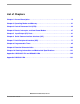
Electrical Characteristics SS (INPUT) SS IS HELD HIGH ON MASTER 1 12 13 13 12 5 SCK (CPOL = 0) (OUTPUT) SEE NOTE SCK (CPOL = 1) (OUTPUT) SEE NOTE 4 5 4 MISO (INPUT) MSB IN BIT 6 - - - -1 LSB IN 11 10 (REF) MOSI (OUTPUT) MASTER MSB OUT 11 (REF) 10 BIT 6 - - - -1 MASTER LSB OUT 13 12 Note: This first clock edge is generated internally but is not seen at the SCK pin. Figure 9-11.
Serial Peripheral Interface Timing SS (INPUT) 1 13 12 12 13 3 5 SCK (CPOL = 0) (INPUT) 4 2 5 SCK (CPOL = 1) (INPUT) 4 8 MISO (OUTPUT) 6 MOSI (INPUT) BIT 6 - - - -1 MSB OUT SLAVE 7 10 SEE NOTE SLAVE LSB OUT 11 11 BIT 6 - - - -1 MSB IN 9 LSB IN Note: Not defined but normally MSB of character just received Figure 9-13.
Electrical Characteristics MC68HC711D3 Data Sheet, Rev. 2.
Chapter 10 Ordering Information and Mechanical Specifications 10.1 Introduction This section provides ordering information for the MC68HC711D3. In addition, mechanical specifications are provided for the following packaging options: • 40-pin plastic dual in-line package (DIP) • 44-pin plastic leaded chip carrier (PLCC) • 44-pin plastic quad flat pack (QFP) 10.2 Ordering Information Table 10-1.
Ordering Information and Mechanical Specifications 10.4 44-Pin PLCC (Case 777-02) -N- Y BRK 0.007(0.180) M T B D L-M S 0.007(0.180) M T U N S L-M S N S Z -M- -L- V 44 W 1 G1 X D 0.010 (0.25) S T VIEW D-D A 0.007(0.180) M T L-M S N S R 0.007(0.180) M T L-M S N S 0.007(0.180) M T H L-M S L-M S N S N S Z J K1 E C 0.004 (0.10) G -TG1 0.010 (0.25) S T L-M S N S K SEATING PLANE F VIEW S 0.007(0.180) M T L-M S N S VIEW S NOTES: 1.
44-Pin QFP (Case 824A-01) 10.5 44-Pin QFP (Case 824A-01) B L B 33 23 22 S D V S 0.20 (0.008) DETAIL A DETAIL A F BASE METAL M H A-B S S C A-B 0.20 (0.008) B L -B- M -A- D -A-, -B-, -D- 0.05 (0.002) A-B 34 J N D 44 0.20 (0.008) 12 1 11 A M C A-B S D S S D S 0.05 (0.002) A-B S 0.20 (0.008) M H A-B M DETAIL C C E -H- -CSEATING PLANE DATUM PLANE 0.01 (0.004) H G M M T DATUM PLANE -H- R K W C A-B S D S SECTION B-B -D0.20 (0.
Ordering Information and Mechanical Specifications MC68HC711D3 Data Sheet, Rev. 2.
Appendix A MC68HC11D3 and MC68HC11D0 A.1 Introduction The MC68HC11D3 and MC68HC11D0 are read-only memory (ROM) based high-performance microcontrollers (MCU) based on the MC68HC11E9 design. Members of the Dx series are derived from the same mask and feature a high-speed multiplexed bus capable of running at up to 3 MHz and a fully static design that allows operations at frequencies to dc. The only difference between the MCUs in the Dx series is whether the ROM has been tested and guaranteed.
MC68HC11D3 and MC68HC11D0 A.
Pin Assignments EXTAL E MODA/LIR MODB/VSTBY 42 41 40 VSS 2 43 PC0 3 XTAL PC1 4 EVSS PC2 5 44 PC3 6 A.
MC68HC11D3 and MC68HC11D0 A.4 Memory Map $0000 $0000 INTERNAL REGISTERS AND I/O (CAN BE MAPPED TO ANY 4-K BOUNDARY $003F USING INIT REGISTER) $0040 192 BYTES STATIC RAM (CAN BE MAPPED TO ANY 4-K BOUNDARY $00FF USING THE INIT REGISTER) $7000 4 KBYTES ROM (MC68HC11D3) PRESENT AT RESET AND CAN BE DISABLED BY $7FFF ROM ON BIT IN CONFIG REGISTER. INTERRUPT VECTORS ARE EXTERNAL.
Ordering Information A.6 Ordering Information MC Order Number MCU MC68HC11D3 (Custom ROM) MC68HC11D0 (No ROM) Package Temperature 2 MHz 3 MHz 44-pin PLCC –40 to +85°C MC68HC11D3CFN2 MC68HC11D3CFN3 44-pin PLCC –40 to +85°C MC68HC11D0CFN2 MC68HC11D0CFN3 44-pin QFP –40 to +85°C MC68HC11D0CFB2 MC68HC11D0CFB3 MC68HC711D3 Data Sheet, Rev. 2.
MC68HC11D3 and MC68HC11D0 MC68HC711D3 Data Sheet, Rev. 2.
Appendix B MC68L11D0 B.1 Introduction The MC68L11D0 is an extended-voltage version of the MC68HC11D0 microcontroller that can operate in applications that require supply voltages as low as 3.0 volts. Operation is identical to that of the MC68HC11D0 (see Appendix A MC68HC11D3 and MC68HC11D0) in all aspects other than electrical parameters, as shown in this appendix.
MC68L11D0 Characteristic(1) Symbol Min Max Unit Input high voltage All inputs except RESET RESET VIH 0.7 x VDD 0.8 x VDD VDD + 0.3 VDD + 0.3 V Input low voltage All inputs VIL VSS – 0.3 0.2 x VDD V I/O ports, three-state leakage PA7, PA3, PC7–PC0, VIn = VIH or VIL PD7–PD0, MODA/LIR, RESET IOZ — ±10 µA Input leakage current VIn = VDD or VSS PA2–PA0, IRQ, XIRQ VIn = VDD or VSS MODB/VSTBY IIn — — ±1 ±10 µA RAM standby voltagePower down VSB 2.
MC68L11D0 Electrical Characteristics B.2.3 Control Timing Characteristic(1) 1.0 MHz Symbol 2.0 MHz Min Max Min Max Unit Frequency of operation fO dc 1.0 dc 2.0 MHz E-clock period tcyc 1000 — 500 — ns Crystal frequency fXTAL — 4.0 — 8.0 MHz External oscillator frequency 4 fO dc 4.0 dc 8.
MC68L11D0 B.2.5 Expansion Bus Timing Characteristic(1) Num Symbol Frequency of operation (E-clock frequency) 1.0 MHz 2.0 MHz Unit Min Max Min Max fO dc 1.0 dc 2.
MC68L11D0 Electrical Characteristics B.2.6 Serial Peripheral Interface Timing Characteristic(1) Num Symbol 1.0 MHz Min Max 2.0 MHz Min Max Unit Operating frequency Master Slave fop(m) fop(s) dc dc 0.5 1.0 dc dc 0.5 2.0 fop MHz 1 Cycle time Master Slave tcyc(m) tCYC(s) 2.0 1000 — — 2.
MC68L11D0 B.3 Ordering Information Package Frequency Features MC Order Number 44-pin PLCC 2 MHz No ROM MC68L11D0FN2 44-pin QFP 2 MHz No ROM MC68L11D0FB2 MC68HC711D3 Data Sheet, Rev. 2.
How to Reach Us: Home Page: www.freescale.com RoHS-compliant and/or Pb- free versions of Freescale products have the functionality and electrical characteristics of their non-RoHS-compliant and/or non-Pb- free counterparts. For further information, see http://www.freescale.com or contact your Freescale sales representative. E-mail: support@freescale.com For information on Freescale.s Environmental Products program, go to http://www.freescale.com/epp.