
Microcontrollers User manual


UM10237_2 © NXP B.V. 2008. All rights reserved.
User manual Rev. 02 — 19 December 2008 667 of 792
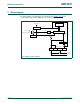
1. Basic configuration
The ADC is configured using the following registers:
1. Power: In the PCONP register (Table 4–63
), set bits PCADC.
Remark: On reset, the ADC is disabled. To enable the ADC, first set the PCADC bit,
and then enable the ADC in the AD0CR register (bit PDN) Table 28–594
. To disable
the ADC, first clear the PDN bit, and then clear the PCADC bit.
2. Clock: In the PCLK_SEL0 register (Table 4–56
), select PCLK_ADC. To scale the
clock for the ADC, see Table 28–594
bits CLKDIV.
3. Pins: Select ADC pins and pin modes in registers PINSELn and PINMODEn (see
Section 9–5
).
4. Interrupts: To enable interrupts in the ADC, see Table 28–597
. Interrupts are enabled
in the VIC using the VICIntEnable register (Section 7–3.4
).
2. Features
• 10 bit successive approximation analog to digital converter.
• Input multiplexing among 8 pins.
• Power down mode.
• Measurement range 0 to 3 V.
• 10 bit conversion time ≥ 2.44 μs.
• Burst conversion mode for single or multiple inputs.
• Optional conversion on transition on input pin or Timer Match signal.
• Individual result registers for each A/D channel to reduce interrupt overhead.
3. Description
Basic clocking for the A/D converters is provided by the APB clock (PCLK). A
programmable divider is included in each converter, to scale this clock to the 4.5 MHz
(max) clock needed by the successive approximation process. A fully accurate conversion
requires 11 of these clocks.
4. Pin description
Table 28–592 gives a brief summary of each of ADC related pins.
UM10237
Chapter 28: LPC24XX Analog-to Digital Converter (ADC)
Rev. 02 — 19 December 2008 User manual