
Microcontrollers User manual


UM10237_2 © NXP B.V. 2008. All rights reserved.
User manual Rev. 02 — 19 December 2008 661 of 792
NXP Semiconductors
UM10237
Chapter 26: LPC24XX Real-Time Clock (RTC) and battery RAM
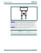
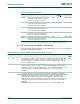
Table 26–584 gives the crystal parameters that should be used. C
L
is the typical load
capacitance of the crystal and is usually specified by the crystal manufacturer. The actual
C
L
influences oscillation frequency. When using a crystal that is manufactured for a
different load capacitance, the circuit will oscillate at a slightly different frequency
(depending on the quality of the crystal) compared to the specified one. Therefore for an
accurate time reference it is advised to use the load capacitors as specified in
Table 26–584
that belong to a specific C
L
. The value of external capacitances C
X1
and
C
X2
specified in this table are calculated from the internal parasitic capacitances and the
C
L
. Parasitics from PCB and package are not taken into account.
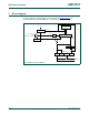
Fig 136. RTC 32 kHz crystal oscillator circuit
Table 584. Recommended values for the RTC external 32 kHz oscillator C
X1/X2
components
Crystal load capacitance
C
L
Maximum crystal series
resistance R
S
External load capacitors C
X1
,
CX2
11 pF < 100 kΩ 18 pF, 18 pF
13 pF < 100 k
Ω 22 pF, 22 pF
15 pF < 100 k
Ω 27 pF, 27 pF
RTCX1 RTCX2
LPC24xx
C
X1
C
X2
32 kHz
Xtal