
Microcontrollers User manual


UM10237_2 © NXP B.V. 2008. All rights reserved.
User manual Rev. 02 — 19 December 2008 614 of 792
NXP Semiconductors
UM10237
Chapter 23: LPC24XX I
2
S interface
[1] Reset Value reflects the data stored in used bits only. It does not include reserved bits content.
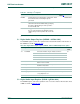
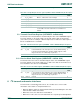
5.1 Digital Audio Output Register (I2SDAO - 0xE008 8000)
The I2SDAO register controls the operation of the I
2
S transmit channel. The function of
bits in DAO are shown in Table 23–532
.
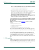
5.2 Digital Audio Input Register (I2SDAI - 0xE008 8004)
The I2SDAI register controls the operation of the I
2
S receive channel. The function of bits
in DAI are shown in Table 23–533
.
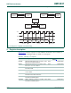
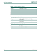
I2SIRQ Interrupt Request Control Register. Contains bits
that control how the I
2
S interrupt request is
generated.
R/W 0xE008 801C
I2STXRATE Transmit bit rate divider. This register
determines the I
2
S transmit bit rate by specifying
the value to divide pclk by in order to produce
the transmit bit clock.
R/W 0xE008 8020
I2SRXRATE Receive bit rate divider. This register determines
the I
2
S receive bit rate by specifying the value to
divide pclk by in order to produce the receive bit
clock.
R/W 0xE008 8024
Table 531. Summary of I
2
S registers
Name Description Access Reset
Value
[1]
Address
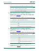
Table 532: Digital Audio Output register (I2SDAO - address 0xE008 8000) bit description
Bit Symbol Value Description Reset
Value
1:0 wordwidth Selects the number of bytes in data as follows: 01
00 8 bit data
01 16 bit data
10 Reserved, do not use this setting
11 32 bit data
2 mono When one, data is of monaural format. When zero, the
data is in stereo format.
0
3 stop Disables accesses on FIFOs, places the transmit
channel in mute mode.
0
4 reset Asynchronously reset the transmit channel and FIFO. 0
5 ws_sel When 0 master mode, when 1 slave mode. 1
14:6 ws_halfperiod Word select half period minus one, i.e. WS 64clk period
-> ws_halfperiod = 31.
0x1F
15 mute When true, the transmit channel sends only zeroes. 1