
Microcontrollers User manual


UM10237_2 © NXP B.V. 2008. All rights reserved.
User manual Rev. 02 — 19 December 2008 576 of 792
NXP Semiconductors
UM10237
Chapter 22: LPC24XX I
2
C interfaces I
2
C0/1/2
6.3 Slave Receiver mode
In the slave receiver mode, data bytes are received from a master transmitter. To initialize
the slave receiver mode, user write the Slave Address Register (I2ADR) and write the I
2
C
Control Set Register (I2CONSET) as shown in Table 22–511
.
I2EN must be set to 1 to enable the I
2
C function. AA bit must be set to 1 to acknowledge
its own slave address or the general call address. The STA, STO and SI bits are set to 0.
After I2ADR and I2CONSET are initialized, the I
2
C interface waits until it is addressed by
its own address or general address followed by the data direction bit. If the direction bit is
0 (W), it enters slave receiver mode. If the direction bit is 1 (R), it enters slave transmitter
mode. After the address and direction bit have been received, the SI bit is set and a valid
status code can be read from the Status Register (I2STAT). Refer to Table 22–527
for the
status codes and actions.
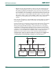
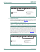
Fig 114. A master receiver switch to master Transmitter after sending repeated START
A = Acknowledge (SDA low)
A = Not acknowledge (SDA high)
S = START condition
P = STOP condition
SLA = Slave Address
DATA
data transferred
(n Bytes + Acknowledge)
From master to slave
From slave to master
A DATA A ASLA R RS W PS SLA DATAAA
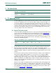
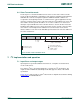
Table 511. I2CnCONSET used to configure Slave mode
Bit 7 6 5 4 3 2 1 0
Symbol - I2EN STA STO SI AA - -
Value- 10001- -
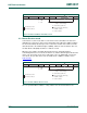
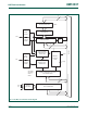
Fig 115. Format of Slave Receiver mode
A
A = Acknowledge (SDA low)
A = Not acknowledge (SDA high)
S = START condition
P = STOP condition
RS = Repeated START condition
A
A/A
data transferred
(n Bytes + Acknowledge)
“0” - write
“1” - read
from Master to Slave
from Slave to Master
S SLAVE ADDRESS W DATA P/RSDATA