
Microcontrollers User manual


UM10237_2 © NXP B.V. 2008. All rights reserved.
User manual Rev. 02 — 19 December 2008 556 of 792
NXP Semiconductors
UM10237
Chapter 21: LPC24XX SD/MMC card interface
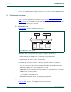
5.3.5 Command format
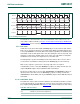
The command path operates in a half-duplex mode, so that commands and responses
can either be sent or received. If the CPSM is not in the SEND state, the MCICMD output
is in HI-Z state, as shown in Figure 21–108
. Data on MCICMD is synchronous to the rising
MCICLK edge. All commands have a fixed length of 48 bits. Table 21–482
shows the
command format.
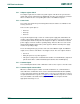
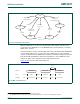
The MCI adapter supports two response types. Both use CRC error checking:
• 48 bit short response (see Table 21–483)
• 136 bit long response (see Table 21–484)
Note: If the response does not contain CRC (CMD1 response), the device driver must
ignore the CRC failed status.
The command register contains the command index (six bits sent to a card) and the
command type. These determine whether the command requires a response, and
whether the response is 48 or 136 bits long (see Section 21–6.4 “
Command Register
(MCICommand - 0xE008 C00C)” for more information). The command path implements
the status flags shown in Table 21–485
(see Section 21–6.11 “Status Register (MCIStatus
- 0xE008 C034)” for more information).
Table 482. Command format
Bit Position Width Value Description
0 1 1 End bit.
7:1 7 - CRC7
39:8 32 - Argument.
45:40 6 - Command index.
46 1 1 Transmission bit.
47 1 0 Stat bit.
Table 483. Simple response format
Bit Position Width Value Description
0 1 1 End bit.
7:1 7 - CRC7 (or 1111111).
39:8 32 - Argument.
45:40 6 - Command index.
46 1 0 Transmission bit.
47 1 0 Start bit.
Table 484. Long response format
Bit Position Width Value Description
0 1 1 End bit.
127:1 127 - CID or CSD (including internal CRC7).
133:128 6 111111 Reserved.
134 1 1 Transmission bit.
135 1 0 Start bit.