
Microcontrollers User manual


UM10237_2 © NXP B.V. 2008. All rights reserved.
User manual Rev. 02 — 19 December 2008 512 of 792
NXP Semiconductors
UM10237
Chapter 18: LPC24XX CAN controllers CAN1/2
17.2.2 Message lost bit and CAN channel number
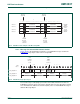
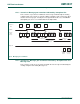
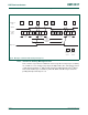
Figure 18–84 is the detailed layout structure of one FullCAN message stored in the
FullCAN message object section of the Look-up Table.
The new message lost bit (MsgLst) is introduced to indicate whether more than one
FullCAN message has been received since last time this message object was read. For
more information the CAN Source Channel (SCC) of the received FullCAN message is
added to Message Object.
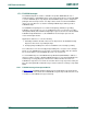
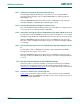
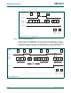
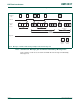
Fig 83. FullCAN section example of the ID look-up table
0
FullCAN
Explicit
Standard
Frame
Format
Identifier
Section
11-bit CAN ID SCC
0
Message
disable bit
Message
disable bit
Index 0, 1
Index 2, 3
Index 4, 5
Index 6, 7
0
SCC 11-bit CAN ID
1234567890
1
112345678901234567890
23
0
11-bit CAN ID SCC
0
SCC 11-bit CAN ID
0
11-bit CAN ID SCC
0
SCC 11-bit CAN ID
0
11-bit CAN ID SCC
0
SCC 11-bit CAN ID
New:
FullCAN
Message
Interrupt
enable bit
New:
FullCAN
Message
Interrupt
enable bit
Fig 84. FullCAN message object layout
31 0
RX Data 4 RX Data 3 RX Data 2 RX Data 1
RX Data 8 RX Data 7 RX Data 6 RX Data 5
9 781516 102324
Msg_ObjAddr + 0
APB
Base +
F
F
RX DLC
R
T
R
S
E
M
0
ID.2
8
ID.1
8
............................
Msg_ObjAddr + 4
Msg_ObjAddr + 8
S
E
M
1
New:
FullCAN
Message
lost bit
SCC
New:
CAN
Source
Channel
un-
used
unused unused