
Microcontrollers User manual


UM10237_2 © NXP B.V. 2008. All rights reserved.
User manual Rev. 02 — 19 December 2008 51 of 792
NXP Semiconductors
UM10237
Chapter 4: LPC24XX Clocking and power control
3.2.6 PLL Status register (PLLSTAT - 0xE01F C088)
The read-only PLLSTAT register provides the actual PLL parameters that are in effect at
the time it is read, as well as the PLL status. PLLSTAT may disagree with values found in
PLLCON and PLLCFG because changes to those registers do not take effect until a
proper PLL feed has occurred (see Section 4–3.2.9 “
PLL Feed register (PLLFEED -
0xE01F C08C)”).
3.2.7 PLL Interrupt: PLOCK
The PLOCK bit in the PLLSTAT register reflects the lock status of the PLL. When the PLL
is enabled, or parameters are changed, the PLL requires some time to establish lock
under the new conditions. PLOCK can be monitored to determine when the PLL may be
18311 3 400.0099
19226 3 419.9984
19775 3 431.9915
20508 3 448.0041
20599 3 449.9920
20874 3 455.9995
21149 3 462.0070
21973 3 480.0075
23071 3 503.9937
23438 3 512.0109
23804 3 520.0063
24170 3 528.0017
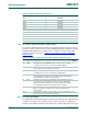
Table 46. Multiplier values for a 32 kHz oscillator
Multiplier (M) Pre-divide (N) F
CCO
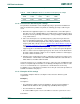
Table 47. PLL Status register (PLLSTAT - address 0xE01F C088) bit description
Bit Symbol Description Reset
value
14:0 MSEL Read-back for the PLL Multiplier value. This is the value currently
used by the PLL, and is one less than the actual multiplier.
0
15 - Reserved, user software should not write ones to reserved bits. The
value read from a reserved bit is not defined.
NA
23:16 NSEL Read-back for the PLL Pre-Divider value. This is the value currently
used by the PLL, and is one less than the actual divider.
0
24 PLLE Read-back for the PLL Enable bit. When one, the PLL is currently
activated. When zero, the PLL is turned off. This bit is automatically
cleared when Power-down mode is activated.
0
25 PLLC Read-back for the PLL Connect bit. When PLLC and PLLE are both
one, the PLL is connected as the clock source for the LPC2400.
When either PLLC or PLLE is zero, the PLL is bypassed. This bit is
automatically cleared when Power-down mode is activated.
0
26 PLOCK Reflects the PLL Lock status. When zero, the PLL is not locked.
When one, the PLL is locked onto the requested frequency. See
text for details.
0
31:27 - Reserved, user software should not write ones to reserved bits. The
value read from a reserved bit is not defined.
NA