
Microcontrollers User manual


UM10237_2 © NXP B.V. 2008. All rights reserved.
User manual Rev. 02 — 19 December 2008 443 of 792
1. Basic configuration
The UART1 peripheral is configured using the following registers:
1. Power: In the PCONP register (Table 4–63
), set bits PCUART1.
Remark: On reset, UART1 is enabled (PCUART1 = 1).
2. Peripheral clock: In the PCLK_SEL0 register (Table 4–56
), select PCLK_UART1.
3. Baud rate: In register U1LCR (Table 17–405
), set bit DLAB =1. This enables access
to registers DLL (Table 17–399
) and DLM (Table 17–400) for setting the baud rate.
Also, if needed, set the fractional baud rate in the fractional divider register
(Table 17–412
).
4. UART FIFO: Use bit FIFO enable (bit 0) in register U0FCR (Table 17–404
) to enable
FIFO.
5. Pins: Select UART pins and pin modes in registers PINSELn and PINMODEn (see
Section 9–5
).
Remark: UART receive pins should not have pull-down resistors enabled.
6. Interrupts: To enable UART interrupts set bit DLAB =0 in register U1LCR
(Table 17–405
). This enables access to U1IER (Table 17–401). Interrupts are enabled
in the VIC using the VICIntEnable register (Table 7–106
).
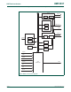
2. Features
• UART1 is identical to UART0/2/3, with the addition of a modem interface.
• 16 byte Receive and Transmit FIFOs.
• Register locations conform to ‘550 industry standard.
• Receiver FIFO trigger points at 1, 4, 8, and 14 bytes.
• Built-in baud rate generator.
• Standard modem interface signals included (CTS, DCD, DTS, DTR, RI, RTS).
• LPC2400 UART1 allows for implementation of either software or hardware flow
control.
UM10237
Chapter 17: LPC24XX Universal Asynchronous
Receiver/Transmitter (UART) 1
Rev. 02 — 19 December 2008 User manual