
Microcontrollers User manual


UM10237_2 © NXP B.V. 2008. All rights reserved.
User manual Rev. 02 — 19 December 2008 402 of 792
NXP Semiconductors
UM10237
Chapter 15: LPC24XX USB OTG controller
2. Free running mode: an interrupt is generated at the end of TIMEOUT_CNT (see
Section 15–7.7 “
OTG Timer Register (OTGTmr - 0xFFE0 C114)”), the TMR bit is set,
and the timer value is reloaded into the counter. The timer is not disabled in this
mode.
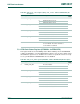
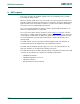
Table 365. OTG Status Control register (OTGStCtrl - address 0xFFE0 C110) bit description
Bit Symbol Description Reset
Value
1:0 PORT_FUNC Controls the function of ports U1 and U2. Bit 0 is set or
cleared by hardware when B_HNP_TRACK or
A_HNP_TRACK is set and HNP succeeds. See
Section 15–8
.
-
3:2 TMR_SCALE Timer scale selection. This field determines the duration
of each timer count.
00: 10
μs (100 KHz)
01: 100
μs (10 KHz)
10: 1000
μs (1 KHz)
11: Reserved
0x0
4 TMR_MODE Timer mode selection.
0: monoshot
1: free running
0
5 TMR_EN Timer enable. When set, TMR_CNT increments. When
cleared, TMR_CNT is reset to 0.
0
6 TMR_RST Timer reset. Writing one to this bit resets TMR_CNT to 0.
This provides a single bit control for the software to
restart the timer when the timer is enabled.
0
7 - Reserved, user software should not write ones to
reserved bits. The value read from a reserved bit is not
defined.
NA
8 B_HNP_TRACK Enable HNP tracking for B-device (peripheral), see
Section 15–8
. Hardware clears this bit when
HNP_SUCCESS or HNP_FAILURE is set.
0
9 A_HNP_TRACK Enable HNP tracking for A-device (host), see
Section 15–8
. Hardware clears this bit when
HNP_SUCCESS or HNP_FAILURE is set.
0
10 PU_REMOVED When the B-device changes its role from peripheral to
host, software sets this bit when it removes the D+
pull-up, see Section 15–8
. Hardware clears this bit when
HNP_SUCCESS or HNP_FAILURE is set.
0
15:11 - Reserved, user software should not write ones to
reserved bits. The value read from a reserved bit is not
defined.
NA
31:16 TMR_CNT Current timer count value. 0x0