
Microcontrollers User manual


UM10237_2 © NXP B.V. 2008. All rights reserved.
User manual Rev. 02 — 19 December 2008 399 of 792
NXP Semiconductors
UM10237
Chapter 15: LPC24XX USB OTG controller
7. Register description
The OTG and I
2
C registers are summarized in the following table.
The Device and Host registers are explained in Section 14–3.2.1
and Section 13–9 in the
USB Device Controller and USB Host (OHCI) Controller chapters. All registers are 32 bits
wide and aligned to word address boundaries.
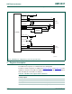
Fig 56. USB OTG port configuration: port U1 host, port U2 device
USB_UP_LED1
USB_D+1
USB_D−1
USB_PWRD1
15
kΩ
15
kΩ
LPC24XX
USB-A
connector
USB-B
connector
33 Ω
33 Ω
33 Ω
33 Ω
002aac710
V
DD
USB_UP_LED2
USB_CONNECT2
V
DD
V
DD
USB_OVRCR1
USB_PPWR1
LM3526-L
ENA
IN
5 V
FLAGA
OUTA
V
DD
D+
D−
D+
D−
V
BUS
USB_D+2
USB_D−2
V
BUS
V
BUS
V
SS
V
SS
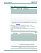
Table 362. USB OTG and I
2
C register address definitions
Name Address Access Function
Interrupt register
USBIntSt 0xE01F C1C0 R/W USB Interrupt Status
OTG registers
OTGIntSt 0xFFE0 C100 RO OTG Interrupt Status
OTGIntEn 0xFFE0 C104 R/W OTG Interrupt Enable