
Microcontrollers User manual


UM10237_2 © NXP B.V. 2008. All rights reserved.
User manual Rev. 02 — 19 December 2008 390 of 792
NXP Semiconductors
UM10237
Chapter 14: LPC24XX USB Host controller
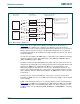
3.1.1 USB host usage note
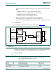
Both ports can be configured as USB hosts. For details on how to connect the USB ports,
see the USB OTG chapter, Section 15–6 “
Pin configuration”.
The USB device/host/OTG controller is disabled after RESET and must be enabled by
writing a 1 to the PCUSB bit in the PCONP register, see Table 4–63
.
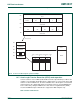
3.2 Software interface
The software interface of the USB host block consists of a register view and the format
definitions for the endpoint descriptors. For details on these two aspects see the OHCI
specification. The register map is shown in the next subsection.
3.2.1 Register map
The following registers are located in the AHB clock ‘cclk’ domain. They can be accessed
directly by the processor. All registers are 32 bit wide and aligned in the word address
boundaries.
USB_INT1 I OTG ATX interrupt External OTG transceiver
USB_SCL1 I/O I
2
C serial clock External OTG transceiver
USB_SDA1 I/O I
2
C serial data External OTG transceiver
U
SB_TX_E1 O Transmit enable External OTG transceiver
USB_TX_DP1 O D+ transmit data External OTG transceiver
USB_TX_DM1 O D
− transmit data External OTG transceiver
USB_RCV1 I Differential receive data External OTG transceiver
USB_RX_DP1 I D+ receive data External OTG transceiver
USB_RX_DM1 I D
− receive data External OTG transceiver
U
SB_LS1 O Low speed status (applies to host functionality only) External OTG transceiver
U
SB_SSPND1 O Bus suspend status External OTG transceiver
U
SB_PPWR1 O Port power enable Host power switch
USB_PWRD1 I Port power status Host power switch
U
SB_OVRCR1 I Over-current status Host power switch
U
SB_HSTEN1 O Host enabled status
Port U2
USB_D+2 I/O Positive differential data USB Connector
USB_D
−2 I/O Negative differential data USB Connector
USB_CONNECT2 O SoftConnect control signal Control
USB_UP_LED2 O GoodLink LED control signal Control
U
SB_PPWR2 O Port power enable Host power switch
U2PWRD2 I Port power status Host power switch
U
SB_OVRCR2 I Over-current status Host power switch
U
SB_HSTEN2 O Host enabled status Control
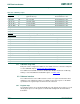
Table 359. USB OTG port pins
Pin name Direction Description Pin category