
Microcontrollers User manual


UM10237_2 © NXP B.V. 2008. All rights reserved.
User manual Rev. 02 — 19 December 2008 375 of 792
NXP Semiconductors
UM10237
Chapter 13: LPC24XX USB device controller
In DMA mode, the bits corresponding to Interrupt on NAK for Bulk OUT and Interrupt OUT
endpoints (INAK_BO and INAK_IO) should be set to 0 using the SIE Set Mode command
(Section 13–11.3
).
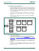
14.4 The DMA descriptor
DMA transfers are described by a data structure called the DMA Descriptor (DD).
DDs are placed in the USB RAM. These descriptors can be located anywhere in the USB
RAM at word-aligned addresses. USB RAM is part of the system memory that is used for
the USB purposes. It is located at address 0x7FD0 0000 and is 8 kB in size.
DDs for non-isochronous endpoints are four words long. DDs for isochronous endpoints
are five words long.
The parameters associated with a DMA transfer are:
• The start address of the DMA buffer
• The length of the DMA buffer
• The start address of the next DMA descriptor
• Control information
• Count information (number of bytes transferred)
• Status information
Table 13–357
lists the DMA descriptor fields.
Table 357. DMA descriptor
Word
position
Access
(H/W)
Access
(S/W)
Bit
position
Description
0 R R/W 31:0 Next_DD_pointer (USB RAM address)
1 R R/W 1:0 DMA_mode (00 -Normal; 01 - ATLE)
R R/W 2 Next_DD_valid (1 - valid; 0 - invalid)
--3Reserved
R R/W 4 Isochronous_endpoint (1 - isochronous;
0 - non-isochronous)
R R/W 15:5 Max_packet_size
R/W
[1]
R/W 31:16 DMA_buffer_length
This value is specified in bytes for non-isochronous
endpoints and in number of packets for isochronous
endpoints.
2 R/W R/W 31:0 DMA_buffer_start_addr