
Microcontrollers User manual


UM10237_2 © NXP B.V. 2008. All rights reserved.
User manual Rev. 02 — 19 December 2008 354 of 792
NXP Semiconductors
UM10237
Chapter 13: LPC24XX USB device controller
Software can also use this register to initiate a DMA transfer to proactively fill an IN
endpoint buffer before an IN token packet is received from the host.
USBDMARSet is a write only register.
The USBDMARSet bit allocation is identical to the USBDMARSt register (Table 13–328
).
9.8.4 USB UDCA Head register (USBUDCAH - 0xFFE0 C280)
The UDCA (USB Device Communication Area) Head register maintains the address
where the UDCA is located in the USB RAM. Refer to Section 13–14.2 “
USB device
communication area” and Section 13–14.4 “The DMA descriptor” for more details on the
UDCA and DMA descriptors. USBUDCAH is a read/write register.
9.8.5 USB EP DMA Status register (USBEpDMASt - 0xFFE0 C284)
Bits in this register indicate whether DMA operation is enabled for the corresponding
endpoint. A DMA transfer for an endpoint can start only if the corresponding bit is set in
this register. USBEpDMASt is a read only register.
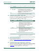
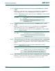
Table 331. USB DMA Request Set register (USBDMARSet - address 0xFFE0 C258) bit
description
Bit Symbol Value Description Reset
value
0 EP0 0 Control endpoint OUT (DMA cannot be enabled for this endpoint
and the EP0 bit must be 0).
0
1 EP1 0 Control endpoint IN (DMA cannot be enabled for this endpoint and
the EP1 bit must be 0).
0
31:2 EPxx Set the endpoint xx (2
≤ xx ≤ 31) DMA request. 0
0 No effect.
1 Set the corresponding bit in USBDMARSt.
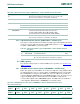
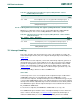
Table 332. USB UDCA Head register (USBUDCAH - address 0xFFE0 C280) bit description
Bit Symbol Description Reset value
6:0 - Reserved. Software should not write ones to reserved bits. The UDCA is
aligned to 128-byte boundaries.
0x00
31:7 UDCA_ADDR Start address of the UDCA. 0
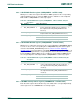
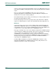
Table 333. USB EP DMA Status register (USBEpDMASt - address 0xFFE0 C284) bit
description
Bit Symbol Value Description Reset
value
0 EP0_DMA_ENABLE 0 Control endpoint OUT (DMA cannot be enabled for
this endpoint and the EP0_DMA_ENABLE bit must
be 0).
0
1 EP1_DMA_ENABLE 0 Control endpoint IN (DMA cannot be enabled for this
endpoint and the EP1_DMA_ENABLE bit must be
0).
0
31:2 EPxx_DMA_ENABLE endpoint xx (2
≤ xx ≤ 31) DMA enabled bit. 0
0 The DMA for endpoint EPxx is disabled.
1 The DMA for endpoint EPxx is enabled.