
Microcontrollers User manual


UM10237_2 © NXP B.V. 2008. All rights reserved.
User manual Rev. 02 — 19 December 2008 338 of 792
NXP Semiconductors
UM10237
Chapter 13: LPC24XX USB device controller
9.3 Device interrupt registers
9.3.1 USB Interrupt Status register (USBIntSt - 0xE01F C1C0)
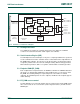
The USB Device Controller has three interrupt lines. This register allows software to
determine their status with a single read operation. All three interrupt lines are ORed
together to a single channel of the vectored interrupt controller. This register also contains
the USB_NEED_CLK status and EN_USB_INTS control bits. USBIntSt is a read/write
register.
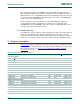
Table 296. USB Clock Status register (USBClkSt - 0xFFE0 CFF8) bit description
Bit Symbol Description Reset
value
0 - Reserved, user software should not write ones to
reserved bits. The value read from a reserved bit is
not defined.
NA
1 DEV_CLK_ON Device clock on. The usbclk input to the device
controller is active.
0
2 - Reserved, user software should not write ones to
reserved bits. The value read from a reserved bit is
not defined.
NA
3 PORTSEL_CLK_ON Port select register clock on. NA
4 AHB_CLK_ON AHB clock on. 0
31:5 - Reserved, user software should not write ones to
reserved bits. The value read from a reserved bit is
not defined.
NA
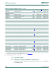
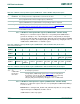
Table 297. USB Interrupt Status register (USBIntSt - address 0xE01F C1C0) bit description
Bit Symbol Description Reset
value
0 USB_INT_REQ_LP Low priority interrupt line status. This bit is read only. 0
1 USB_INT_REQ_HP High priority interrupt line status. This bit is read only. 0
2 USB_INT_REQ_DMA DMA interrupt line status. This bit is read only. 0
7:3 - Reserved, user software should not write ones to reserved bits. The
value read from a reserved bit is not defined.
NA