
Microcontrollers User manual


UM10237_2 © NXP B.V. 2008. All rights reserved.
User manual Rev. 02 — 19 December 2008 281 of 792
NXP Semiconductors
UM10237
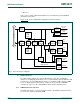
Chapter 12: LPC24XX LCD controller
• 256 entry, 16-bit palette RAM, arranged as a 128x32-bit RAM.
• Frame, line, and pixel clock signals.
• AC bias signal for STN, data enable signal for TFT panels.
• Supports little and big-endian, and Windows CE data formats.
• LCD panel clock may be generated from the peripheral clock, or from a clock input
pin.
4.1 Programmable parameters
The following key display and controller parameters can be programmed:
• Horizontal front and back porch
• Horizontal synchronization pulse width
• Number of pixels per line
• Vertical front and back porch
• Vertical synchronization pulse width
• Number of lines per panel
• Number of pixel clocks per line
• Hardware cursor control.
• Signal polarity, active HIGH or LOW
• AC panel bias
• Panel clock frequency
• Bits-per-pixel
• Display type: STN monochrome, STN color, or TFT
• STN 4 or 8-bit interface mode
• STN dual or single panel mode
• Little-endian, big-endian, or Windows CE mode
• Interrupt generation event
4.2 Hardware cursor support
The hardware cursor feature reduces software overhead associated with maintaining a
cursor image in the LCD frame buffer.
Without this feature, software needed to:
• Save an image of the area under the next cursor position.
• Update the area with the cursor image.
• Repair the last cursor position with a previously saved image.
In addition, the LCD driver had to check whether the graphics operation had overwritten
the cursor, and correct it. With a cursor size of 64x64 and 24-bit color, each cursor move
involved reading and writing approximately 75KB of data.