
Microcontrollers User manual


UM10237_2 © NXP B.V. 2008. All rights reserved.
User manual Rev. 02 — 19 December 2008 216 of 792
NXP Semiconductors
UM10237
Chapter 11: LPC24XX Ethernet
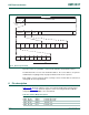
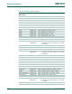
A packet consists of a preamble, a start-of-frame delimiter and an Ethernet frame.
The Ethernet frame consists of the destination address, the source address, an optional
VLAN field, the length/type field, the payload and the frame check sequence.
Each address consists of 6 bytes where each byte consists of 8 bits. Bits are transferred
starting with the least significant bit.
6. Pin description
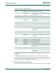
Table 11–183 shows the signals used for connecting the Media Independent Interface
(MII), and Table 11–184
shows the signals used for connecting the Reduced Media
Independent Interface (RMII) to the external PHY.
Fig 27. Ethernet packet fields
OPTIONAL
VLAN
SOURCE
ADDRESS
DesA
oct6
DesA
oct1
DesA
oct2
DesA
oct3
DesA
oct4
DesA
oct5
SrcA
oct6
SrcA
oct5
SrcA
oct4
SrcA
oct3
SrcA
oct2
SrcA
oct1
LSB
oct(0)
oct(1) oct(2) oct(3) oct(4) oct(5) oct(6)
MSB
oct(7)
DESTINATION
ADDRESS
PAYLOAD FCS
ETHERNET FRAME
PREAMBLE
7 bytes
ethernet packet
start-of-frame
delimiter
1 byte
time
LEN
TYPE
Table 183. Ethernet MII pin descriptions
Pin Name Type Pin Description
ENET_TX_EN Output Transmit data enable.
ENET_TXD[3:0] Output Transmit data, 4 bits.
ENET_TX_ER Output Transmit error.
ENET_TX_CLK Input Transmit clock.