
Microcontrollers User manual


UM10237_2 © NXP B.V. 2008. All rights reserved.
User manual Rev. 02 — 19 December 2008 154 of 792
NXP Semiconductors
UM10237
Chapter 8: LPC24XX Pin configuration
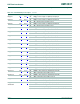
[2] 5 V tolerant pad providing digital I/O functions (with TTL levels and hysteresis) and analog input. When configured as a ADC input,
digital section of the pad is disabled.
[3] 5 V tolerant pad providing digital I/O with TTL levels and hysteresis and analog output function. When configured as the DAC output,
digital section of the pad is disabled.
[4] Open-drain 5 V tolerant digital I/O pad, compatible with I
2
C-bus 400 kHz specification. It requires an external pull-up to provide output
functionality. When power is switched off, this pin connected to the I
2
C-bus is floating and does not disturb the I
2
C lines. Open-drain
configuration applies to all functions on this pin.
[5] Pad provides digital I/O and USB functions. It is designed in accordance with the USB specification, revision 2.0 (Full-speed and
Low-speed mode only).
[6] 5 V tolerant pad with 5 ns glitch filter providing digital I/O functions with TTL levels and hysteresis.
[7] 5 V tolerant pad with 20 ns glitch filter providing digital I/O function with TTL levels and hysteresis.
[8] Pad provides special analog functionality.
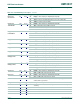
5. LPC2470/78 pinning information
Table 123. LPC2470/78 pin allocation table
Pin Symbol Pin Symbol Pin Symbol Pin Symbol
Row A
1 P3[27]/D27/
CAP1[0]/PWM1[4]
2V
SSIO
3 P1[0]/ENET_TXD0 4 P4[31]/CS1
5 P1[4]/ENET_TX_EN 6 P1[9]/ENET_RXD0 7 P1[14]/ENET_RX_ER 8 P1[15]/
ENET_REF_CLK/
ENET_RX_CLK
9 P1[17]/ENET_MDIO 10 P1[3]/ENET_TXD3/
MCICMD/PWM0[2]
11 P4[15]/A15 12 V
SSIO
13 P3[20]/D20/
PWM0[5]/DSR1
14 P1[11]/ENET_RXD2/
MCIDAT2/PWM0[6]
15 P0[8]/I2STX_WS/
LCDVD[16]/MISO1/
MAT2[2]
16 P1[12]/ENET_RXD3/
MCIDAT3/PCAP0[0]
17 P1[5]/ENET_TX_ER/
MCIPWR/PWM0[3]
---
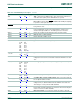
Row B
1 P3[2]/D2 2 P3[10]/D10 3 P3[1]/D1 4 P3[0]/D0
5 P1[1]/ENET_TXD1 6 V
SSIO
7 P4[30]/CS0 8 P4[24]/OE
9 P4[25]/WE 10 P4[29]/BLS3/MAT2[1]/
LCDVD[7]/LCDVD[11]/
LCDVD[3]/RXD3
11 P1[6]/ENET_TX_CLK/
MCIDAT0/PWM0[4]
12 P0[4]/I2SRX_CLK/
LCDVD[0]/RD2/CAP2[0]
13 V
DD(3V3)
14 P3[19]/D19/
PWM0[4]/DCD1
15 P4[14]/A14 16 P4[13]/A13
17 P2[0]/PWM1[1]/TXD1/
TRACECLK/LCDPWR
---
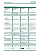
Row C
1 P3[13]/D13 2 TDI 3 RTCK 4 P0[2]/TXD0
5 P3[9]/D9 6 P3[22]/D22/
PCAP0[0]/RI1
7 P1[8]/ENET_CRS_DV/
ENET_CRS
8 P1[10]/ENET_RXD1
9V
DD(3V3)
10 P3[21]/D21/
PWM0[6]/DTR1
11 P4[28]/BLS2/MAT2[0]/
LCDVD[6]/LCDVD[10]/
LCDVD[2]/TXD3
12 P0[5]/I2SRX_WS/
LCDVD[1]/TD2/CAP2[1]