
Microcontrollers User manual


UM10237_2 © NXP B.V. 2008. All rights reserved.
User manual Rev. 02 — 19 December 2008 119 of 792
1. How to read this chapter
For information about the individual LPC2400 parts, refer to table Table 8–118. Parts
LPC2460 and LPC2470 are flashless and use pins P3[15] and P3[14] for boot control.
See the PINSEL registers (Section 9–3) to configure the pins of each LPC2400 part for
the desired function.
2. LPC2400 pin packages
2.1 LPC2400 180-pin package
UM10237
Chapter 8: LPC24XX Pin configuration
Rev. 02 — 19 December 2008 User manual
Table 118. LPC2400 pin configurations overview
Part Pins Pin packages Pin allocation Pin description Boot control
LQFP208 TFBGA180/208 TFBGA180/208
LPC2458 180 - Figure 8–23 Table 8–119 Table 8–120 n/a
LPC2420/60 208 Figure 8–24
Figure 8–25 Table 8–121 Table 8–122 Section 8–6
LPC2468 208 Figure 8–24 Figure 8–25 Table 8–121 Table 8–122 n/a
LPC2470 208 Figure 8–24
Figure 8–25 Table 8–124 Table 8–124 Section 8–6
LPC2478 208 Figure 8–24 Figure 8–25 Table 8–124 Table 8–124 n/a
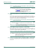
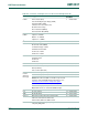
Fig 23. LPC2458 pinning TFBGA180 package
002aad094
LPC2458
2 4 6 8 10 12 13 141357911
ball A1
index area
P
N
M
L
K
J
G
E
H
F
D
C
B
A
Transparent top view