
Datasheet


LPC178X_7X All information provided in this document is subject to legal disclaimers. © NXP Semiconductors N.V. 2014. All rights reserved.
Product data sheet Rev. 5 — 9 September 2014 97 of 122
NXP Semiconductors
LPC178x/7x
32-bit ARM Cortex-M3 microcontroller
13. DAC electrical characteristics
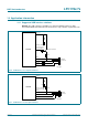
The values of resistor components R
cmp
and R
sw
vary with temperature and input voltage and are
process-dependent.
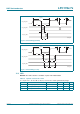
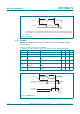
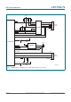
Fig 29. ADC interface to pins ADC0_IN[n]
Table 30. ADC interface components
Component Range Description
R
cmp
90 to 300 Switch-on resistance for the comparator input switch. Varies
with temperature, input voltage, and process.
R
sw
500 to 2 k Switch-on resistance for channel selection switch. Varies with
temperature, input voltage, and process.
C1 110 fF Parasitic capacitance from the ADC block level.
C2 80 fF Parasitic capacitance from the ADC block level.
C3 1.6 pF Sampling capacitor.
LPC178x/7x
AD0[n]
110 fF
80 fF
C
ia
1.6 pF
R
vsi
R
sw
500 Ω - 2 kΩ
R
cmp
90 Ω - 300 Ω
V
SS
V
EXT
002aag613
ADC
COMPARATOR
BLOCK
C1
C3
C2
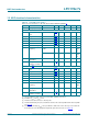
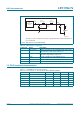
Table 31. 10-bit DAC electrical characteristics
V
DDA
= 2.7 V to 3.6 V; T
amb
=
40
C to +85
C unless otherwise specified
Symbol Parameter Min Typ Max Unit
E
D
differential linearity error - 1- LSB
E
L(adj)
integral non-linearity - 1.5 - LSB
E
O
offset error - 0.6 - %
E
G
gain error - 0.6 - %
C
L
load capacitance - - 200 pF
R
L
load resistance 1 - - k