
Datasheet
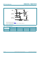
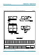
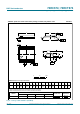
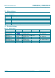
Table Of Contents
- 1. General description
- 2. Features and benefits
- 3. Ordering information
- 4. Functional diagram
- 5. Pinning information
- 6. Functional description
- 7. Limiting values
- 8. Recommended operating conditions
- 9. Static characteristics
- 10. Dynamic characteristics
- 11. Waveforms
- 12. Package outline
- 13. Abbreviations
- 14. Revision history
- 15. Legal information
- 16. Contact information
- 17. Contents
74HC_HCT574 All information provided in this document is subject to legal disclaimers. © NXP Semiconductors N.V. 2015. All rights reserved.
Product data sheet Rev. 6 — 26 January 2015 11 of 19
NXP Semiconductors
74HC574; 74HCT574
Octal D-type flip-flop; positive edge-trigger; 3-state
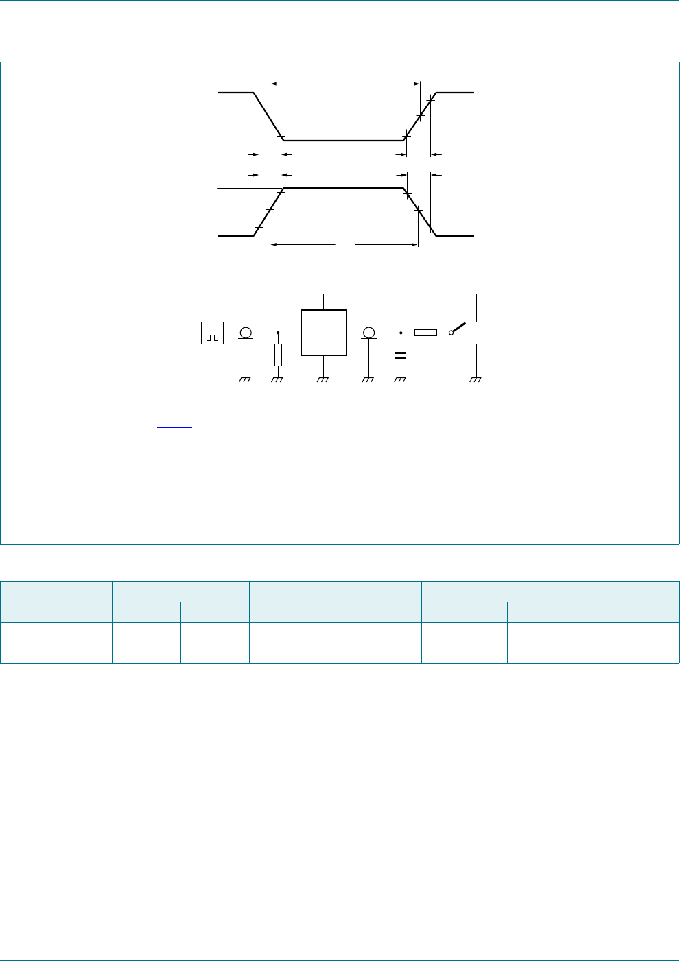
Test data is given in Table 9.
Definitions test circuit:
R
T
= Termination resistance should be equal to output impedance Z
o
of the pulse generator.
C
L
= Load capacitance including jig and probe capacitance.
R
L
= Load resistance.
S1 = Test selection switch.
Fig 10. Test circuit for measuring switching times
9
0
9
0
W
:
W
:
9
9
,
9
,
QHJDWLYH
SXOVH
SRVLWLYH
SXOVH
9
9
0
9
0
W
I
W
U
W
U
W
I
DDG
'87
9
&&
9
&&
9
,
9
2
5
7
5
/
6
&
/
RSHQ
*
Table 9. Test data
Type Input Load S1 position
V
I
t
r
, t
f
C
L
R
L
t
PHL
, t
PLH
t
PZH
, t
PHZ
t
PZL
, t
PLZ
74HC574 V
CC
6ns 15pF, 50 pF 1k open GND V
CC
74HCT574 3 V 6 ns 15 pF, 50 pF 1 k open GND V
CC