
Datasheet


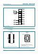
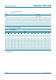

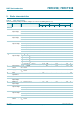
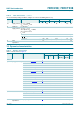
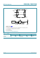
Table Of Contents
- 1. General description
- 2. Features
- 3. Ordering information
- 4. Functional diagram
- 5. Pinning information
- 6. Functional description
- 7. Limiting values
- 8. Recommended operating conditions
- 9. Static characteristics
- 10. Dynamic characteristics
- 11. Waveforms
- 12. Package outline
- 13. Abbreviations
- 14. Revision history
- 15. Legal information
- 16. Contact information
- 17. Contents
74HC_HCT238_3 © NXP B.V. 2007. All rights reserved.
Product data sheet Rev. 03 — 16 July 2007 8 of 18
NXP Semiconductors
74HC238; 74HCT238
3-to-8 line decoder/demultiplexer
[1] t
pd
is the same as t
PHL
and t
PLH
.
[2] t
t
is the same as t
THL
and t
TLH
.
[3] C
PD
is used to determine the dynamic power dissipation (P
D
in µW):
P
D
=C
PD
× V
CC
2
× f
i
× N+∑ (C
L
× V
CC
2
× f
o
) where:
f
i
= input frequency in MHz;
f
o
= output frequency in MHz;
C
L
= output load capacitance in pF;
V
CC
= supply voltage in V;
N = number of inputs switching;
∑ (C
L
× V
CC
2
× f
o
) = sum of outputs.
11. Waveforms
74HCT238
t
pd
propagation delay An to Yn; see Figure 6
[1]
V
CC
= 4.5 V - 19 35 44 53 ns
V
CC
= 5.0 V; C
L
=15pF - 18 - - - ns
E3 to Yn; see
Figure 6
[1]
V
CC
= 4.5 V - 20 37 46 56 ns
V
CC
= 5.0 V; C
L
=15pF - 20 - - - ns
En to Yn or see Figure 7
[1]
V
CC
= 4.5 V - 20 35 44 53 ns
V
CC
= 5.0 V; C
L
=15pF - 21 - - - ns
t
t
transition time V
CC
= 4.5 V;
see
Figure 6 and Figure 7
[2]
- 7 15 19 22 ns
C
PD
power dissipation
capacitance
per package;
V
I
= GND to V
CC
− 1.5 V
[3]
-76- - -pF
Table 7. Dynamic characteristics
GND = 0 V; test circuit see Figure 8.
Symbol Parameter Conditions 25 °C −40 °C to +125 °C
Min Typ Max Max
(85 °C)
Max
(125 °C)
Unit
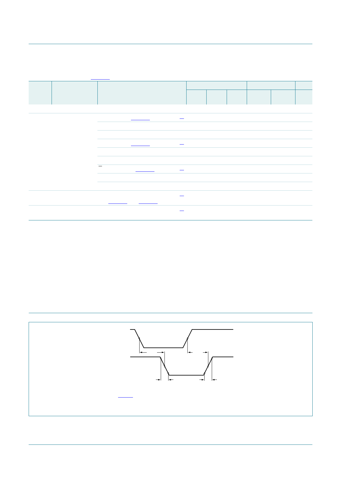
Measurement points are given in Table 8.
V
OL
and V
OH
are typical voltage output levels that occur with the output load.
Fig 6. Input (An, E3) to output (Yn) propagation delays and output transition times
001aag757
An, E3 input
Yn output
t
THL
t
TLH
V
M
V
M
V
X
V
Y
t
PHL
t
PLH