
User Manual
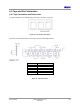
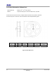
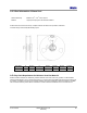
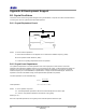
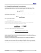
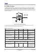
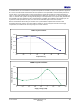
Table Of Contents
- 1 Introduction
- 2 Pin Configurations
- 3 CPU
- 4 Memory Organisation
- 5 System Clocks
- 6 Reset
- 7 Interrupt System
- 8 Wireless Transceiver
- 9 Digital Input/Output
- 10 Serial Peripheral Interface
- 11 Timers
- 12 Pulse Counters
- 13 Serial Communications
- 14 JTAG Debug Interface
- 15 Two-Wire Serial Interface
- 16 Four-Wire Digital Audio Interface
- 17 Random Number Generator
- 18 Sample FIFO
- 19 Intelligent Peripheral Interface
- 20 Analogue Peripherals
- 21 Power Management and Sleep Modes
- 22 Electrical Characteristics
- 22.1 Maximum Ratings
- 22.2 DC Electrical Characteristics
- 22.3 AC Characteristics
- 22.3.1 Reset and Voltage Brown-Out
- 22.3.2 SPI MasterTiming
- 22.3.3 Intelligent Peripheral (SPI Slave) Timing
- 22.3.4 Two-wire Serial Interface
- 22.3.5 Four-Wire Digital Audio Interface
- 22.3.6 Wakeup and Boot Load Timings
- 22.3.7 Bandgap Reference
- 22.3.8 Analogue to Digital Converters
- 22.3.9 Digital to Analogue Converters
- 22.3.10 Comparators
- 22.3.11 32kHz RC Oscillator
- 22.3.12 32kHz Crystal Oscillator
- 22.3.13 32MHz Crystal Oscillator
- 22.3.14 24MHz RC Oscillator
- 22.3.15 Temperature Sensor
- 22.3.16 Radio Transceiver
- Appendix A Mechanical and Ordering Information
- Appendix B Development Support

Jennic
© Jennic 2009 JN-DS-JN5148-001 1v2 89
Preliminary
As is stated above, not all combinations of crystal load capacitance and ESR are valid, and as explained in Appendix
B.1.3 there is a trade-off that exists between the load capacitance and crystal ESR to achieve reliable performance.
For this reason, we recommend that for a 9pF load capacitance crystals be specified with a maximum ESR of 40
ohms. For lower load capacitances the recommended maximum ESR rises, for example, CL=7pF the max ESR is 61
ohms. For the lower cost crystals in the large HC49 package, a load capacitance of 9 or 10pF is widely available and
the max ESR of 30 ohms specified by many manufacturers is acceptable. Also available in this package style, are
crystals with a load capacitance of 12pF, but in this case the max ESR required is 25 ohms or better.
Below is measurement data showing the variation of the crystal oscillator amplifier transconductance with
temperature and supply voltage, notice how small the variation is. Circuit techniques have been used to apply
compensation, such that the user need only design for nominal conditions.
32MHz Crystal Oscillator
4.1
4.15
4.2
4.25
4.3
4.35
-40 -20 0 20 40 60 80 100
Temperature (C)
Transconductance (mA/V)
32MHz Crystal Oscillator
4.28
4.29
4.3
4.31
2 2.2 2.4 2.6 2.8 3 3.2 3.4 3.6
Supply Voltage (VDD)
Transconductance (mA/V)