
User Manual
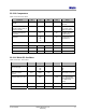
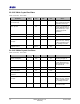
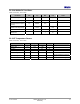
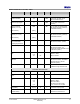
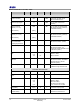
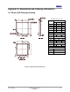
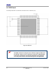
Table Of Contents
- 1 Introduction
- 2 Pin Configurations
- 3 CPU
- 4 Memory Organisation
- 5 System Clocks
- 6 Reset
- 7 Interrupt System
- 8 Wireless Transceiver
- 9 Digital Input/Output
- 10 Serial Peripheral Interface
- 11 Timers
- 12 Pulse Counters
- 13 Serial Communications
- 14 JTAG Debug Interface
- 15 Two-Wire Serial Interface
- 16 Four-Wire Digital Audio Interface
- 17 Random Number Generator
- 18 Sample FIFO
- 19 Intelligent Peripheral Interface
- 20 Analogue Peripherals
- 21 Power Management and Sleep Modes
- 22 Electrical Characteristics
- 22.1 Maximum Ratings
- 22.2 DC Electrical Characteristics
- 22.3 AC Characteristics
- 22.3.1 Reset and Voltage Brown-Out
- 22.3.2 SPI MasterTiming
- 22.3.3 Intelligent Peripheral (SPI Slave) Timing
- 22.3.4 Two-wire Serial Interface
- 22.3.5 Four-Wire Digital Audio Interface
- 22.3.6 Wakeup and Boot Load Timings
- 22.3.7 Bandgap Reference
- 22.3.8 Analogue to Digital Converters
- 22.3.9 Digital to Analogue Converters
- 22.3.10 Comparators
- 22.3.11 32kHz RC Oscillator
- 22.3.12 32kHz Crystal Oscillator
- 22.3.13 32MHz Crystal Oscillator
- 22.3.14 24MHz RC Oscillator
- 22.3.15 Temperature Sensor
- 22.3.16 Radio Transceiver
- Appendix A Mechanical and Ordering Information
- Appendix B Development Support

Jennic
© Jennic 2009 JN-DS-JN5148-001 1v2 77
Preliminary
Radio Parameters: 2.0-3.6V, +85ºC
Parameter Min Typical Max Unit Notes
Receiver Characteristics
Receive sensitivity -93 dBm Nominal for 1% PER, as per
802.15.4 section 6.5.3.3
Maximum input signal +3 dBm For 1% PER, measured as
sensitivity
Adjacent channel
rejection (-1/+1 ch)
[CW Interferer]
19/34
[TBC]
dBc For 1% PER, with wanted signal
3dB, above sensitivity. (Note1,2)
(modulated interferer)
Alternate channel
rejection (-2 / +2 ch)
[CW Interferer]
40/45
[TBC]
dBc For 1% PER, with wanted signal
3dB, above sensitivity. (Note1,2)
(modulated interferer)
Other in band rejection
2.4 to 2.4835 GHz,
excluding adj channels
49 dBc For 1% PER with wanted signal
3dB above sensitivity. (Note1)
Out of band rejection 53 dBc For 1% PER with wanted signal
3dB above sensitivity. All
frequencies except wanted/2 which
is 8dB lower. (Note1)
Spurious emissions
(RX)
<-70
-62
-59
dBm Measured conducted into 50ohms
30MHz to 1GHz
1GHz to 12GHz
Intermodulation
protection
41 dB For 1% PER at with wanted signal
3dB above sensitivity. Modulated
Interferers at 2 & 4 channel
separation (Note1)
RSSI linearity -4 +4 dB -95 to -10dBm.
Available through Hardware API
Transmitter Characteristics
Transmit power +1.8 dBm
Output power control
range
-35 dB In three 12dB steps (Note3)
Spurious emissions
(TX)
<-70
-40
<-70
dBm Measured conducted into 50ohms
30MHz to 1GHz,
1GHz to12.5GHz,
The following exceptions apply
1.8 to 1.9GHz & 5.15 to 5.3GHz
EVM [Offset] 10 [2.0] 15 % At maximum output power
Transmit Power
Spectral Density
-38 -20 dBc At greater than 3.5MHz offset, as
per 802.15.4, section 6.5.3.1