
User Manual
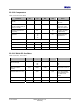
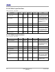
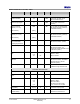
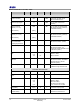
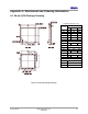
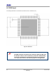
Table Of Contents
- 1 Introduction
- 2 Pin Configurations
- 3 CPU
- 4 Memory Organisation
- 5 System Clocks
- 6 Reset
- 7 Interrupt System
- 8 Wireless Transceiver
- 9 Digital Input/Output
- 10 Serial Peripheral Interface
- 11 Timers
- 12 Pulse Counters
- 13 Serial Communications
- 14 JTAG Debug Interface
- 15 Two-Wire Serial Interface
- 16 Four-Wire Digital Audio Interface
- 17 Random Number Generator
- 18 Sample FIFO
- 19 Intelligent Peripheral Interface
- 20 Analogue Peripherals
- 21 Power Management and Sleep Modes
- 22 Electrical Characteristics
- 22.1 Maximum Ratings
- 22.2 DC Electrical Characteristics
- 22.3 AC Characteristics
- 22.3.1 Reset and Voltage Brown-Out
- 22.3.2 SPI MasterTiming
- 22.3.3 Intelligent Peripheral (SPI Slave) Timing
- 22.3.4 Two-wire Serial Interface
- 22.3.5 Four-Wire Digital Audio Interface
- 22.3.6 Wakeup and Boot Load Timings
- 22.3.7 Bandgap Reference
- 22.3.8 Analogue to Digital Converters
- 22.3.9 Digital to Analogue Converters
- 22.3.10 Comparators
- 22.3.11 32kHz RC Oscillator
- 22.3.12 32kHz Crystal Oscillator
- 22.3.13 32MHz Crystal Oscillator
- 22.3.14 24MHz RC Oscillator
- 22.3.15 Temperature Sensor
- 22.3.16 Radio Transceiver
- Appendix A Mechanical and Ordering Information
- Appendix B Development Support

Jennic
72 JN-DS-JN5148-001 1v2 © Jennic 2009
Preliminary
22.3.12 32kHz Crystal Oscillator
VDD = 2.0 to 3.6V, -40 to +85ºC
Parameter Min Typ Max Unit Notes
Current consumption of cell
and counter logic
1.5 µA This is sensitive to the ESR
of the crystal,Vdd and total
capacitance at each pin
Start – up time 0.8 s Assuming xtal with ESR of
les than 40kohms and CL=
9pF External caps = 15pF
(Vdd/2mV pk-pk) see
Appendix B
Input capacitance 1.4 pF Bondpad and package
Transconductance 17 uA/V
External Capacitors
(CL=9pF)
15 pF Total external capacitance
needs to be 2*CL, allowing
for stray capacitance from
chip, package and PCB
Amplitude at Xout Vdd-0.2 Vp-p
22.3.13 32MHz Crystal Oscillator
VDD = 2.0 to 3.6V, -40 to +85ºC
Parameter Min Typ Max Unit Notes
Current consumption 400 µA Excluding bandgap ref.
Start – up time 0.84 ms Assuming xtal with ESR of
les than 40ohms and CL=
9pF External caps = 15pF
see
Appendix B
Input capacitance 1.4 pF Bondpad and package
Transconductance 4.3 mA/V
DC voltages, XTALIN,
XTALOUT
430/470 mV
External Capacitors
(CL=9pF)
15 pF Total external capacitance
needs to be 2*CL, allowing
for stray capacitance from
chip, package and PCB
Amplitude detect threshold 320 mVp-p Threshold detection
accessible via API