
User Manual
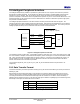
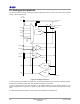
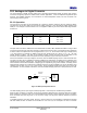
Table Of Contents
- 1 Introduction
- 2 Pin Configurations
- 3 CPU
- 4 Memory Organisation
- 5 System Clocks
- 6 Reset
- 7 Interrupt System
- 8 Wireless Transceiver
- 9 Digital Input/Output
- 10 Serial Peripheral Interface
- 11 Timers
- 12 Pulse Counters
- 13 Serial Communications
- 14 JTAG Debug Interface
- 15 Two-Wire Serial Interface
- 16 Four-Wire Digital Audio Interface
- 17 Random Number Generator
- 18 Sample FIFO
- 19 Intelligent Peripheral Interface
- 20 Analogue Peripherals
- 21 Power Management and Sleep Modes
- 22 Electrical Characteristics
- 22.1 Maximum Ratings
- 22.2 DC Electrical Characteristics
- 22.3 AC Characteristics
- 22.3.1 Reset and Voltage Brown-Out
- 22.3.2 SPI MasterTiming
- 22.3.3 Intelligent Peripheral (SPI Slave) Timing
- 22.3.4 Two-wire Serial Interface
- 22.3.5 Four-Wire Digital Audio Interface
- 22.3.6 Wakeup and Boot Load Timings
- 22.3.7 Bandgap Reference
- 22.3.8 Analogue to Digital Converters
- 22.3.9 Digital to Analogue Converters
- 22.3.10 Comparators
- 22.3.11 32kHz RC Oscillator
- 22.3.12 32kHz Crystal Oscillator
- 22.3.13 32MHz Crystal Oscillator
- 22.3.14 24MHz RC Oscillator
- 22.3.15 Temperature Sensor
- 22.3.16 Radio Transceiver
- Appendix A Mechanical and Ordering Information
- Appendix B Development Support

Jennic
52 JN-DS-JN5148-001 1v2 © Jennic 2009
Preliminary
18 Sample FIFO
A 10 deep FIFO is provided to buffer data between the CPU and either the four-wire digital audio interface or the
DAC/ ADC. It supports single channel input and output data, up to 16 bits wide. When used it can reduce the rate at
which the processor has to generate/process data, and this may allow more efficient operation. Interrupts can be
generated based on fill levels and also FIFO empty and full conditions. Normal configuration of the digital audio
interface or the DAC/ ADC is still required when accessing the data via the FIFO.
When used with the DAC / ADC functions a timing signal is generated by the DAC/ ADC functions to control the
transfer of data to and from the FIFO and the analogue peripherals. The transfers will occur at the sample rate
configured within the DAC / ADC functions.
When the FIFO is linked to the four-wire digital audio interface, timer 2 must be used to generate an internal timing
signal to control the flow of data across the interface. The timer does not require any external pins to be enabled. The
timer should be set up to produce a PWM output with a rising edge generated every time a digital audio transfer is
required. The transfer rate is typically configured to be the audio sample rate, e.g. 8kHz. If the transfer rate is too fast
or slow data will be transferred correctly between the FIFO and the digital audio block.