
User Manual
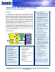
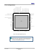
Table Of Contents
- 1 Introduction
- 2 Pin Configurations
- 3 CPU
- 4 Memory Organisation
- 5 System Clocks
- 6 Reset
- 7 Interrupt System
- 8 Wireless Transceiver
- 9 Digital Input/Output
- 10 Serial Peripheral Interface
- 11 Timers
- 12 Pulse Counters
- 13 Serial Communications
- 14 JTAG Debug Interface
- 15 Two-Wire Serial Interface
- 16 Four-Wire Digital Audio Interface
- 17 Random Number Generator
- 18 Sample FIFO
- 19 Intelligent Peripheral Interface
- 20 Analogue Peripherals
- 21 Power Management and Sleep Modes
- 22 Electrical Characteristics
- 22.1 Maximum Ratings
- 22.2 DC Electrical Characteristics
- 22.3 AC Characteristics
- 22.3.1 Reset and Voltage Brown-Out
- 22.3.2 SPI MasterTiming
- 22.3.3 Intelligent Peripheral (SPI Slave) Timing
- 22.3.4 Two-wire Serial Interface
- 22.3.5 Four-Wire Digital Audio Interface
- 22.3.6 Wakeup and Boot Load Timings
- 22.3.7 Bandgap Reference
- 22.3.8 Analogue to Digital Converters
- 22.3.9 Digital to Analogue Converters
- 22.3.10 Comparators
- 22.3.11 32kHz RC Oscillator
- 22.3.12 32kHz Crystal Oscillator
- 22.3.13 32MHz Crystal Oscillator
- 22.3.14 24MHz RC Oscillator
- 22.3.15 Temperature Sensor
- 22.3.16 Radio Transceiver
- Appendix A Mechanical and Ordering Information
- Appendix B Development Support

Jennic
© Jennic 2009 JN-DS-JN5148-001 1v2 5
Preliminary
A.5.2 Reel Information: 180mm Reel 84
A.5.3 Reel Information: 330mm Reel 85
A.5.4 Dry Pack Requirement for Moisture Sensitive Material 85
Appendix B Development Support 86
B.1 Crystal Oscillators 86
B.1.1 Crystal Equivalent Circuit 86
B.1.2 Crystal Load Capacitance 86
B.1.3 Crystal ESR and Required Transconductance 87
B.2 32MHz Oscillator 88
B.3 32kHz Oscillator 90
B.4 JN5148 Module Reference Designs 92
B.4.1 Schematic Diagram 92
B.4.2 PCB Design and Reflow Profile 94
Related Documents 95
RoHS Compliance 95
Status Information 95
Disclaimers 96
Version Control 96
Contact Details 97