
User Manual
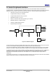
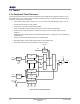
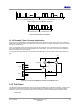
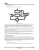
Table Of Contents
- 1 Introduction
- 2 Pin Configurations
- 3 CPU
- 4 Memory Organisation
- 5 System Clocks
- 6 Reset
- 7 Interrupt System
- 8 Wireless Transceiver
- 9 Digital Input/Output
- 10 Serial Peripheral Interface
- 11 Timers
- 12 Pulse Counters
- 13 Serial Communications
- 14 JTAG Debug Interface
- 15 Two-Wire Serial Interface
- 16 Four-Wire Digital Audio Interface
- 17 Random Number Generator
- 18 Sample FIFO
- 19 Intelligent Peripheral Interface
- 20 Analogue Peripherals
- 21 Power Management and Sleep Modes
- 22 Electrical Characteristics
- 22.1 Maximum Ratings
- 22.2 DC Electrical Characteristics
- 22.3 AC Characteristics
- 22.3.1 Reset and Voltage Brown-Out
- 22.3.2 SPI MasterTiming
- 22.3.3 Intelligent Peripheral (SPI Slave) Timing
- 22.3.4 Two-wire Serial Interface
- 22.3.5 Four-Wire Digital Audio Interface
- 22.3.6 Wakeup and Boot Load Timings
- 22.3.7 Bandgap Reference
- 22.3.8 Analogue to Digital Converters
- 22.3.9 Digital to Analogue Converters
- 22.3.10 Comparators
- 22.3.11 32kHz RC Oscillator
- 22.3.12 32kHz Crystal Oscillator
- 22.3.13 32MHz Crystal Oscillator
- 22.3.14 24MHz RC Oscillator
- 22.3.15 Temperature Sensor
- 22.3.16 Radio Transceiver
- Appendix A Mechanical and Ordering Information
- Appendix B Development Support

Jennic
40 JN-DS-JN5148-001 1v2 © Jennic 2009
Preliminary
• 28-bit match value
• Maskable timer interrupt
• Single-shot, Restartable or Continuous modes of operation
Match Value
Counter
=
Mode
Control
&
&
SysClk
Run
Match
Int
Enable
Tick Timer
Interrupt
Reset
Mode
Figure 28: Tick Timer
The Tick Timer is clocked from a continuous 16MHz clock, which is fed to a 32-bit wide resettable up-counter, gated
by a signal from the mode control block. A match register allows comparison between the counter and a
programmed value. The match value, measured in 16MHz clock cycles is programmed through software, in the
range 0 to 0x0FFFFFFF. The output of the comparison can be used to generate an interrupt if the interrupt is
enabled and used in controlling the counter in the different modes. Upon configuring the timer mode, the counter is
also reset.
If the mode is programmed as single shot, the counter begins to count from zero until the match value is reached.
The match signal will be generated which will cause an interrupt if enabled, and the counter will stop counting. The
counter is restarted by reprogramming the mode.
If the mode is programmed as restartable, the operation of the counter is the same as for the single shot mode,
except that when the match value is reached the counter is reset and begins counting from zero. An interrupt will be
generated when the match value is reached if it is enabled.
Continuous mode operation is similar to restartable, except that when the match value is reached, the counter is not
reset but continues to count. An interrupt will be generated when the match value is reached if enabled.
11.3 Wakeup Timers
Two 32-bit wakeup timers are available in the JN5148 driven from the 32kHz internal clock. They may run during
sleep periods when the majority of the rest of the device is powered down, to time sleep periods or other long period
timings that may be required by the application. The wakeup timers do not run during deep sleep and may optionally
be disabled in sleep mode through software control. When a wakeup timer expires it typically generates an interrupt,
if the device is asleep then the interrupt may be used as an event to end the sleep period. See Section
21 for further
details on how they are used during sleep periods. Features include:
• 35-bit down-counter
• Optionally runs during sleep periods
• Clocked by 32kHz system clock; either 32kHz RC oscillator, 32kHz XTAL oscillator or 32kHz clock input