
User Manual
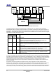
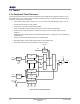
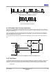
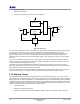
Table Of Contents
- 1 Introduction
- 2 Pin Configurations
- 3 CPU
- 4 Memory Organisation
- 5 System Clocks
- 6 Reset
- 7 Interrupt System
- 8 Wireless Transceiver
- 9 Digital Input/Output
- 10 Serial Peripheral Interface
- 11 Timers
- 12 Pulse Counters
- 13 Serial Communications
- 14 JTAG Debug Interface
- 15 Two-Wire Serial Interface
- 16 Four-Wire Digital Audio Interface
- 17 Random Number Generator
- 18 Sample FIFO
- 19 Intelligent Peripheral Interface
- 20 Analogue Peripherals
- 21 Power Management and Sleep Modes
- 22 Electrical Characteristics
- 22.1 Maximum Ratings
- 22.2 DC Electrical Characteristics
- 22.3 AC Characteristics
- 22.3.1 Reset and Voltage Brown-Out
- 22.3.2 SPI MasterTiming
- 22.3.3 Intelligent Peripheral (SPI Slave) Timing
- 22.3.4 Two-wire Serial Interface
- 22.3.5 Four-Wire Digital Audio Interface
- 22.3.6 Wakeup and Boot Load Timings
- 22.3.7 Bandgap Reference
- 22.3.8 Analogue to Digital Converters
- 22.3.9 Digital to Analogue Converters
- 22.3.10 Comparators
- 22.3.11 32kHz RC Oscillator
- 22.3.12 32kHz Crystal Oscillator
- 22.3.13 32MHz Crystal Oscillator
- 22.3.14 24MHz RC Oscillator
- 22.3.15 Temperature Sensor
- 22.3.16 Radio Transceiver
- Appendix A Mechanical and Ordering Information
- Appendix B Development Support

Jennic
36 JN-DS-JN5148-001 1v2 © Jennic 2009
Preliminary
11 Timers
11.1 Peripheral Timer/Counters
Three general-purpose timer/counter units are available that can be independently configured to operate in one of
five possible modes. Timer 0 and 1 support all 5 modes of operation and Timer 2 supports PWM and Delta-Sigma
modes only. The timers have the following:
• 5-bit prescaler, divides system clock by 2
prescale
value
as the clock to the timer (prescaler range is 0 to 16)
• Clocked from internal system clock (16MHz)
• 16-bit counter, 16-bit Rise and Fall (period) registers
• Timer: can generate interrupts off Rise and Fall counts. Can be gated by external signal
• Counter: counts number of transitions on external event signal. Can use low-high, high-low or both
transitions
• PWM/Single pulse: outputs repeating Pulse Width Modulation signal or a single pulse. Can set period and
mark-space ratio
• Capture: measures times between transitions of an applied signal
• Delta-Sigma: Return-To-Zero (RTZ) and Non-Return-to-Zero (NRZ) modes
• Timer usage of external IO can be controlled on a pin by pin basis
Interrupt
Generator
Rise
Fall
Delta-Sigma
Counter
Reset Generator
=
Prescaler
INT
Int Enable
SYSCLK
S/w
Reset
System
Reset
Single
Shot
=
S
R
OE
Gate
Gate
Edge
Select
Reset
PWM/Delta-
Sigma
Capture
Generator
Capture
Enable
PWM/Δ−Σ
PWM/Δ−Σ
TIMxCK_GT
TIMxOUT
TIMxCAP
Figure 22: Timer Unit Block Diagram