
User Manual
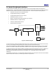
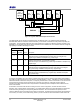
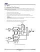
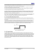
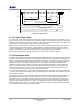
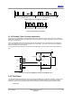
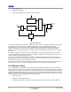
Table Of Contents
- 1 Introduction
- 2 Pin Configurations
- 3 CPU
- 4 Memory Organisation
- 5 System Clocks
- 6 Reset
- 7 Interrupt System
- 8 Wireless Transceiver
- 9 Digital Input/Output
- 10 Serial Peripheral Interface
- 11 Timers
- 12 Pulse Counters
- 13 Serial Communications
- 14 JTAG Debug Interface
- 15 Two-Wire Serial Interface
- 16 Four-Wire Digital Audio Interface
- 17 Random Number Generator
- 18 Sample FIFO
- 19 Intelligent Peripheral Interface
- 20 Analogue Peripherals
- 21 Power Management and Sleep Modes
- 22 Electrical Characteristics
- 22.1 Maximum Ratings
- 22.2 DC Electrical Characteristics
- 22.3 AC Characteristics
- 22.3.1 Reset and Voltage Brown-Out
- 22.3.2 SPI MasterTiming
- 22.3.3 Intelligent Peripheral (SPI Slave) Timing
- 22.3.4 Two-wire Serial Interface
- 22.3.5 Four-Wire Digital Audio Interface
- 22.3.6 Wakeup and Boot Load Timings
- 22.3.7 Bandgap Reference
- 22.3.8 Analogue to Digital Converters
- 22.3.9 Digital to Analogue Converters
- 22.3.10 Comparators
- 22.3.11 32kHz RC Oscillator
- 22.3.12 32kHz Crystal Oscillator
- 22.3.13 32MHz Crystal Oscillator
- 22.3.14 24MHz RC Oscillator
- 22.3.15 Temperature Sensor
- 22.3.16 Radio Transceiver
- Appendix A Mechanical and Ordering Information
- Appendix B Development Support

Jennic
34 JN-DS-JN5148-001 1v2 © Jennic 2009
Preliminary
SI
SO
C
SS
Slave 0
Flash/
EEPROM
Me mor y
JN5148
37
38
41
42
43
36
33
34
SI
SO
C
SS
Slave 1
Us er
Def ined
SI
SO
C
SS
Slave 2
Us er
Def ined
SI
SO
C
SS
Slave 3
Us er
Defined
SI
SO
C
SS
Slave 4
Us er
Def ined
SPIMISO
SPIMOSI
SPICLK
SPISEL 4
SPISEL2
SPISEL3
SPISEL 1
SPISEL0
Figure 20: Typical JN5148 SPI Peripheral Connection
The data transfer rate on the SPI bus is determined by the SPICLK signal. The JN5148 supports transfers at
selectable data rates from 16MHz to 125kHz selected by a clock divider. Both SPICLK clock phase and polarity are
configurable. The clock phase determines which edge of SPICLK is used by the JN5148 to present new data on the
SPIMOSI line; the opposite edge will be used to read data from the SPIMISO line. The interface should be configured
appropriately for the SPI slave being accessed.
SPICLK
Polarity
(CPOL)
Phase
(CPHA)
Mode Description
0
0 0 SPICLK is low when idle – the first edge is positive.
Valid data is output on SPIMOSI before the first clock and changes every
negative edge. SPIMISO is sampled every positive edge.
0
1 1 SPICLK is low when idle – the first edge is positive.
Valid data is output on SPIMOSI every positive edge. SPIMISO is sampled every
negative edge.
1
0 2 SPICLK is high when idle – the first edge is negative.
Valid data is output on SPIMOSI before the first clock edge and is changed
every positive edge. SPIMISO is sampled every negative edge.
1
1 3 SPICLK is high when idle – the first edge is negative.
Valid data is output on SPIMOSI every negative edge. SPIMISO is sampled
every positive edge.
Table 3 SPI Configurations
If more than one SPISEL line is to be used in a system they must be used in numerical order starting from SPISEL0.
For instance if 3 SPI select lines are to be used, they must be SPISEL0, 1 and 2. A SPISEL line can be automatically
deasserted between transactions if required, or it may stay asserted over a number of transactions. For devices such
as memories where a large amount of data can be received by the master by continually providing SPICLK
transitions, the ability for the select line to stay asserted is an advantage since it keeps the slave enabled over the
whole of the transfer.
A transaction commences with the SPI bus being set to the correct configuration, and then the slave device is
selected. Upon commencement of transmission (1 to 32 bits) data is placed in the FIFO data buffer and clocked out,
at the same time generating the corresponding SPICLK transitions. Since the transfer is full-duplex, the same
number of data bits is being received from the slave as it transmits. The data that is received during this transmission
can be read (1 to 32 bits). If the master simply needs to provide a number of SPICLK transitions to allow data to be