
User Manual
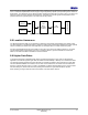
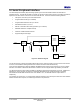
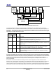
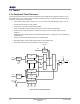
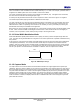
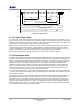
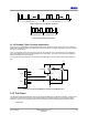
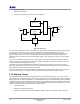
Table Of Contents
- 1 Introduction
- 2 Pin Configurations
- 3 CPU
- 4 Memory Organisation
- 5 System Clocks
- 6 Reset
- 7 Interrupt System
- 8 Wireless Transceiver
- 9 Digital Input/Output
- 10 Serial Peripheral Interface
- 11 Timers
- 12 Pulse Counters
- 13 Serial Communications
- 14 JTAG Debug Interface
- 15 Two-Wire Serial Interface
- 16 Four-Wire Digital Audio Interface
- 17 Random Number Generator
- 18 Sample FIFO
- 19 Intelligent Peripheral Interface
- 20 Analogue Peripherals
- 21 Power Management and Sleep Modes
- 22 Electrical Characteristics
- 22.1 Maximum Ratings
- 22.2 DC Electrical Characteristics
- 22.3 AC Characteristics
- 22.3.1 Reset and Voltage Brown-Out
- 22.3.2 SPI MasterTiming
- 22.3.3 Intelligent Peripheral (SPI Slave) Timing
- 22.3.4 Two-wire Serial Interface
- 22.3.5 Four-Wire Digital Audio Interface
- 22.3.6 Wakeup and Boot Load Timings
- 22.3.7 Bandgap Reference
- 22.3.8 Analogue to Digital Converters
- 22.3.9 Digital to Analogue Converters
- 22.3.10 Comparators
- 22.3.11 32kHz RC Oscillator
- 22.3.12 32kHz Crystal Oscillator
- 22.3.13 32MHz Crystal Oscillator
- 22.3.14 24MHz RC Oscillator
- 22.3.15 Temperature Sensor
- 22.3.16 Radio Transceiver
- Appendix A Mechanical and Ordering Information
- Appendix B Development Support

Jennic
32 JN-DS-JN5148-001 1v2 © Jennic 2009
Preliminary
9 Digital Input/Output
There are 21 Digital I/O (DIO) pins, which can be configured as either an input or an output, and each has a
selectable internal pull-up resistor. Most DIO pins are multiplexed with alternate peripheral features of the device,
see section 2.1. Once a peripheral is enabled it takes precedence over the device pins. Refer to the individual
module sections for a full description of the alternate peripherals functions. Following a reset (and whilst the reset
input is held low), all peripherals are off and the DIO pins are configured as inputs with the internals pull-ups turned
on.
When a peripheral is not enabled, the DIO pins associated with it can be used as digital inputs or outputs. Each pin
can be controlled individually by setting the direction and then reading or writing to the pin.
The individual pull-up resistors, R
PU
, can also be enabled or disabled as needed and the setting is held through sleep
cycles. The pull-ups are generally configured once after reset depending on the external components and
functionality. For instance, outputs should generally have the pull-ups disabled. An input that is always driven should
also have the pull-up disabled.
When configured as an input each pin can be used to generate an interrupt upon a change of state (selectable
transition either from low to high or high to low); the interrupt can be enabled or disabled. When the device is
sleeping, these interrupts become events that can be used to wake the device up. Equally the status of the interrupt
may be read. See section
21 Power Management and Sleep Modes for further details on sleep and wakeup.
The state of all DIO pins can be read, irrespective of whether the DIO is configured as an input or an output.
Throughout a sleep cycle the direction of the DIO, and the state of the outputs, is held. This is based on the resultant
of the GPIO Data/ Direction registers and the effect of any enabled peripherals at the point of entering sleep.
Following a wake-up these directions and output values are maintained under control of the GPIO data / direction
registers. Any peripherals enabled before the sleep cycle are not automatically re-enabled, this must be done through
software after the wake-up.
For example, if DIO0 is configured to be SPISEL1 then it becomes an output. The output value is controlled by the
SPI functional block. If the device then enters a sleep cycle, the DIO will remain an output and hold the value being
output when entering sleep. After wake-up the DIO will still be an output with the same value but controlled from the
GPIO Data/Direction registers. It can be altered with the software functions that adjust the DIO, or the application may
re-configure it to be SPISEL1.
Unused DIO pins are recommended to be set as inputs with the pull-up enabled.